FFSD PCB Connectors – High Density Solutions for Connectivity
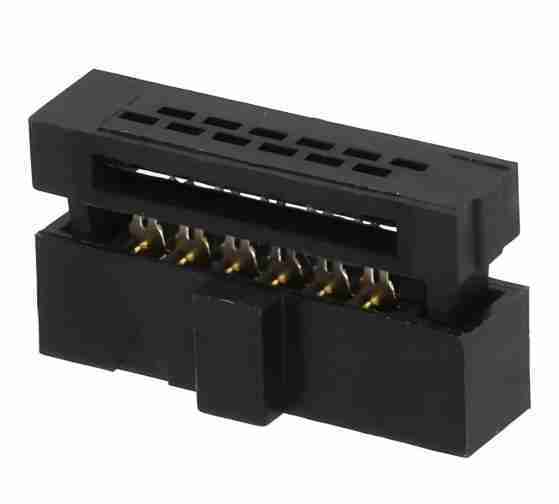
Table of Conent
Table of Conent
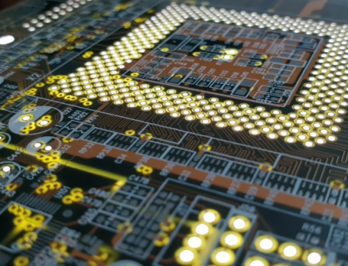
FFSD connectors are high performance, high reliability printed circuit board connectors that are used to connect flat flexible cables (FFC/FPC), to flexible printed circuits. FFC/FPC connectors can adapt to different shapes and sizes and are flexible. The connector was designed for electronic devices that require compact and high density connections. This device’s main goal is to effectively transmit electrical signals while minimising electromagnetic interferance (EMI) to ensure reliable and stable transmission.
A FFSD PCB Connector is made up of two parts.
The connector body: Usually made from plastic or another insulating material, with a locking system to secure the cable in place.
Metal contacts: These are used to contact the metal conductor wiring on the FFC/FPC in order to transmit signal or power.
What Is a Connector PCB?
A PCB connector connects and secures a printed circuit (PCB). The pin-press-in design has a superior clamping force for FPC cables. It is primarily used for board-toboard connections in order to provide a reliable and precise electrical connection. Plug-and-play (easy to connect, replace) and solder (stable, but difficult to replace) are the three most common types of connections.
What Is an FFSD PCB Connector?
FFSD connectors have specific housings and contact systems. They also feature unique locking mechanisms and compact housings. To ensure connection stability, reliability and adapt to specific application scenarios.
The FFSD connectors were designed for flexible connections to shielded cables. They are able to provide a high level of performance in environments that require high interference immunity, compact layouts and efficient connections for flexible flat cables and flexible printed circuits.
The majority of FFSD cables consist of flexible, flex-resistant material. These connectors have a double row of pins with a distance between them of 0.050 inches (1.27mm) to meet different signal transmission needs.
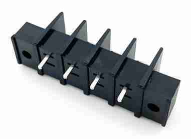
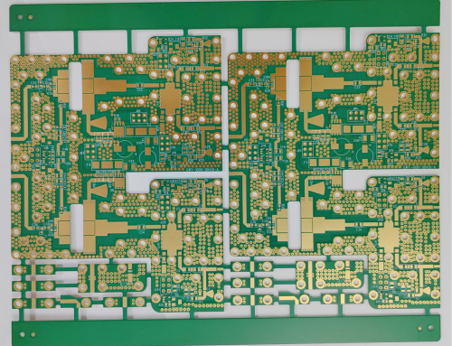
What’s the Structure of FFSD PCB Connector?
The connectors have a double row of pins with a distance between them of 0.050 inches (1.27mm) to meet different signal transmission needs. Pin counts can range from 3 to 25 and are suitable for a variety of circuit connections. Connector housings are often made of insulating plastics like PBT to protect internal components and facilitate alignment. They also incorporate features such as locking mechanisms for secure connection.
Cable mounting is a common mounting technique, in which the connector and cable can be joined by soldering, crimping or other methods, before the cable is attached on the PCB to transmit the signal. Some FFSD Connectors support surface mount technology, where the connector can be soldered directly on the surface of the board. This allows for different circuit layouts or design requirements.
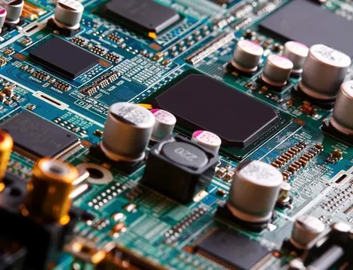
What Are the Common PCB Connectors?
The most common PCB connectors are: Connectors with a male socket and a female pin, and a flexible metal plating. These are used to connect circuit boards and components.
USB connectors of Type A, B, and C are used to link circuit boards with components. These connectors transmit data and power using internal metal tabs. These connectors can also be used to charge electronic devices or transfer data.
HDMI connectors have shielding, multiple pins and are capable of transmitting audio and video in high definition.
SATA Connectors are used for serial data transfers. Both the data and power interfaces are present. This component is necessary to connect optical drives and hard disks with motherboards.
D-Sub Connector is also known as VGA Connector. It has multiple pins that transmit analog video signals. This connector is still used in older equipment and low-resolution environments to connect monitors and computers.
RJ45 Connector is equipped with 8 metal contacts on the inside for Ethernet connection. This is an essential part for wired network communication, such as the computer NIC and router LAN interface.
How Do you Choose a Plug in Connector?
When selecting PCB connectors, there are a few key things to keep in mind:
Understand the technical requirements for the application. This includes pin spacing, the soldering technique, the rated voltage and current, the number of plugs/unplugs, the temperature range, the board spacing, the connector geometry, the solder hole diameters on the tabs.
Contact resistance, insulation resistance and current limiting are all electrical properties of connectors.
Check the dimensions of the mounting space and the connector. Pay attention to the pins during the SMT procedure.
Packaging is important for automated assembly. The two most common packaging types are strip boxes and tape-and-reel packaging. The first is better for high-volume production. Tips on selecting PCB connectors: Female and Pin headers are common, cheap and ideal for large devices. It is also convenient and inexpensive.
Tips for Selecting Different Types of PCB Connectors:
Pin and Female headers is common and cheap, and suitable for large devices. The advantage is that it is convenient and cheap. However, the disadvantage is its large size.
High-end Board-to-Board Connectors are small and have many pins. They are suitable for compact products. The disadvantage is the high price and inability to plug-in/unplug frequently.
The thickened board to board connector is perfect for development and test boards. The connector is easy to connect and measure, but its downside is the large volume.
FPC connectors connect mother boards and daughter boards. The connectors are small, flexible and expensive. The FFSD PCB Connector’s Operating Principle The FFSD connector can be explained as follows: The FFC/FPC cable is inserted into the connector slot, and the conductive conductors on the cable are connected to the contacts of the connector. Many FFSD connectors feature a locking mechanism that prevents cables from coming out of the connector or falling out. After inserting and locking the FFC/FPC cable, the electrical signal is transmitted to the PCB through the connector contacts. The connector acts as a transmission bridge.
How Does the FFSD Connector Work?
FFSD connectors are based primarily on the manufacture and design of printed circuit boards, which are composed of printed components and circuits or a combination thereof. They are also pre-engineered to include insulating materials for the purpose of realizing the electrical connection between the electronic components.
The PCB connectors’ exact working mechanism is:
Metal wires and wires are used on the PCB to connect electronic components. The circuit’s electrical requirements are met by arranging and designing parameters such as wire path, width, and spacing.
PCBs anchor electronic components and provide mechanical support. They can be secured by soldering or insertion, and they ensure relative position and stability.
Wires and circuits on a PCB transmit signals to electronic devices. Factors such as noise rejection and interconnect lengths are taken into consideration to ensure stable transmission of signal and to reduce interference.
PCB connectors do not have to be traditional terminal blocks or pin connectors. These connectors are available in different forms such as BGA and SMT .
These connectors improve miniaturization, reliability, and integration in electronic products. PCB connectors have been widely used as carriers to connect, support, and manage electronic components in various electronic devices.
What Is the Advantage of FFSD PCB Connectors?
The main advantages of FFSD pcb connectors are:
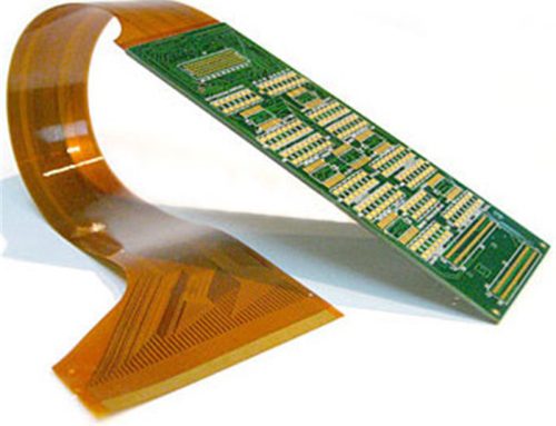
Firstly the cable is adaptable and flexible. FFC/FPC Connectors can be bent and moved in a limited space when connected to FFC/FPC cables. The connectors can be adapted to fit different shapes and sizes of circuit boards.
The cable is also excellent at reducing electromagnetic interference in high-frequency environments, thanks to the shielding layer that’s applied on the surface. The cable is stable and reliable in its signal transmission, allowing the equipment to operate normally in complex electromagnetic environments.
The connector’s locking mechanism is also highly reliable. It can prevent the cable from falling out of place due to vibrations or shocks. It improves the durability and reliability of the electronic system by ensuring a stable connection.
The connector has good electrical performance. It is also highly customizable. The FFSD connectors are designed to meet specific requirements for applications, including cable length, width and bending angles, as well as the number of pins.
Which Applications do FFSD PCB Connectors Have?
FFSD PCB connector is also known as FFC/FPC connector.
It has a variety of uses, mainly for consumer electronics. In medical electronics, the connector is used to facilitate data processing and acquisition for small and portable devices. It is used in industrial control. It connects the key components of automated production lines, instrumentation and communication equipment to enhance production and equipment performance. It is applicable to communication equipment, such as base stations, optical communications, routers, etc. It is used to adapt high-speed communication requirements and ensure stable transmission of signals. Aeronautics: It is used in avionics, satellite communication and other equipment that requires reliable operation and signal stability. This ensures flight and communication safety.
FFSD PCB Connector is a high-performance and reliable electronic component which plays a crucial role in electronic equipment. It is widely used in consumer electronics, automotive electronics, industrial control equipment and communication equipment.
Common FFSD PCB Connector Models
• Molex 51110 Series
Features include 0.5mm pitch connections for high density and reliability . The series offers multiple locking options for a secure connection between FFC/FPC cables. Cell phones, laptops and tablets are all possible applications.
• Samtec FTSH Series
Features include zero insertion force (ZIF) for easy plugging in and unplugging of high density electronic devices. They are compatible with FFC/FPC cable sizes ranging from 0.5mm to 2.0mm. Applications include industrial automation, sensors, display devices, etc.
• The TE Connectivity Series 2182837
Features include a high-density, low-profile design that supports FFC/FPC connectors with pitches of 0.5mm to 1.25mm. These connectors have precision metal contacts to ensure stable signal transmission. These connectors are used in automotive electronics, consumer electronics of high quality and medical devices.
• Hirose Electric’s FH12 Series
• Features include a variety of pitch options (0.5mm and 1.0mm). Support for ZIF technology is supported, as well as easy installation and high reliability. Used for transmission of high-frequency signals. Applications include HDTVs, digital cameras, portable devices, etc.
• JST ZHR Series
FFC/FPC connectors are available with pitches ranging from 0.5mm to 1.0mm. They feature low contact resistance, stable performance and a wide range of pitch options. This connector is ideal for lightweight consumer electronics. Applications include computers, home appliances, robot control, etc.
• Amphenol FCI Series 10142900
Features include the highly-integrated design of this connector. This series supports FFC/FPC connection with 0.5mm or 1.0mm pitch. Its durable latch design also ensures a safe connection. Applications include medical devices, smart homes, car navigation systems, etc.
• Kyocera 0001012
Features include a 0.5mm pitch connector that supports microelectronic device high-current signaling and high-frequency. Applications includeLaptop computers, cell phones, wearable devices, etc.
• Phoenix Contact 1844606 Series
Features include FFC/FPC connectors for 0.8mm or 1.0mm pitches, compact design, and high interference immunity. Suitable for industrial environments. Applications include Industrial automation, robotics, control panels, etc.
• Fujitsu’s 37320-xxxx Series
Features high density connectors. This high density connector series supports 0.5mm or 1.0mm pitch and is widely used for high-performance consumer electronic devices. It has good durability and anti interference performance. Applications include various portable devices, in-car entertainment systems, etc.
• Yamaichi Electronics’ 870-xx Series
Features include excellent electrical performance, reliability and support for high precision applications. High-end communication equipments, medical electronics, testing equipment, etc.
FFSD Connectors Compared to Other PCB Connectors
FFSD connecters are smaller than traditional PCB connections such as pin connectors and standard DIP connectors. FFSD connectors offer a more flexible connection. FFSD connectors can connect to flexible cables, such as FFC/FPC. Conventional connectors are used more often for rigid cables and PCBs. FFSD connectors require less effort to install. The Zero Insertion Force (ZIF), which is a design of FFSD connectors, simplifies the plugging and unplugging process and reduces damag.
Conclusion
FFSD PCB connectors are an important part of modern electronic devices. Compact designs, high signaling efficiency, and immunity to interference make them ideal for high-density connectors. FFSD connectors have been used for decades in automotive, industrial and medical applications. They are also known for their flexibility, reliability and miniaturization. FFSD PCB Connectors are expected to continue to play an important role, as electronic devices require more functionality and space.
Latest Blog


Contact Info
Phone: +86-755-82882936
Email: [email protected]
WhatsApp: +86-13570802455
Wechat: +86-13570802455
Address: 2nd floor,D Bldg.,Electric Link Technology Bldg.,Gongming,Guangming New Dist.,518106 Shenzhen, China