Reflow Soldering – A Key Point of Printed Circuit Assembly
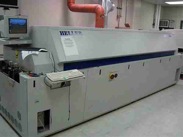
Table of Conent
Table of Conent
One common technique for making SMT complete circuit boards is reflow soldering. The PCB that the components will be positioned on is covered with solder paste. Solder paste is applied to the PCB card on which the components will be placed. After that, the electronic board is heated in a reflow oven while being closely watched. The component leads are attached to the assembled circuit board’s pads using melted solder paste. The solder solidifies and the connection is made when the board cools.
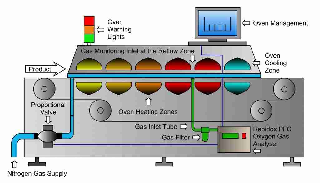
Three steps make up the widely utilized reflow soldering procedure. The assembled circuit board is gradually heated to a temperature that melts the solder paste during the preheating stage. The paste achieves its melting point during the melting phase, which varies from 180°C to 250°C depending on the solder. The solder solidifies and creates the required joint during the cooling process. To get a high-quality solder junction, it’s critical to maintain the proper temperature profile.
Typical Reflow Soldering Challenges
Despite its popularity and usefulness, reflow soldering has drawbacks. Maximum temperature control is necessary at every stage of the procedure, including timing and placement. Soldering flaws can result from even minor changes to these parameters. The most frequent issues and difficulties with reflow soldering, along with their fixes, will be discussed in the conversation that follows.
1. Joints of Cold Solder
Weak and partial solder junctions between component leads and circuit boards are the result of cold solder joints, which happen when the solder melts in reflow incompletely. Signal integrity problems and electrical failures may result from these solder connections!
An inaccurate or arbitrary setting of the reflow oven’s maximum temperature might also result in cold solder connections. Furthermore, the PCB output rate and temperature need to be accurate. Preventing cold solder connections requires a steady and consistent temperature profile. Reliable soldering may also be achieved by applying the solder paste correctly and utilizing the best paste for the electronic card component.
2. Blow Holes
Residual air pockets in a solder joint are known as blowholes, also called voids. These voids weaken the solder joint and cause it to fail. Blowholes are most likely to occur when there is insufficient flux or improper heating.
To prevent porosity, there must be enough flux in the solder paste.
This reduces the chance of voids by improving the solder’s flow. Additionally, trapped air can be avoided by tailoring the reflow oven’s temperature profile. For example, regular heating of the circuit board helps avoid blowholes during the reflow process.
3. Insufficient Solder
Insufficient solder is caused by low solder paste on the PCB pads or poor flow of solder paste during the heating process. This factor can cause solder joints to fail easily.
To avoid under-soldering, the pads must be properly aligned and the solder paste supplied in the right quantity. Precision solder paste printers and premium stencils can be used to accomplish this. Additionally, the solder paste can be adequately melted and flowing by regulating the oven’s heating profile, which will leave a sufficient amount of solder at the joint.
4. Solder Bridging
When two adjacent pads have too much solder on them, an accidental connection known as a solder bridge is formed. This problem can be brought on by using too much solder paste, improper component placement, or incorrect reflow profiles. Using the correct ingredients and the precise amount of solder paste is essential to preventing solder bridging. Additionally, you must modify the temperature profile of the reflow oven. This will guarantee that the solder paste melts uniformly and that no excess solder adheres to adjacent electronic cards. Examining the circuit board for excess solder paste before the reflow procedure is another method of detecting solder bridging.
5. Flux Residue
The chemical residue that remains after flux is used to manufacture solder paste is known as flux residue. These can damage your assembled circuit board and possibly lead to corrosion or failure if you don’t deal with them.
By applying the proper flux and cleaning the board after reflow, you may lessen flux residue. The kind of flux you use determines the kind of cleaning solution you use. It is very important to follow the instructions of the manufacturer for removing flux residue to make sure you get the best results.
6. Inconsistent Reflow Profiles
Cold solder connections, inadequate solder, and blowholes are examples of problems that can result from inconsistent temperature profiles during reflow. To accomplish homogeneous soldering, precise reflow temperature profiles are necessary.
Reflow ovens should be calibrated regularly to keep the reflow temperature profile constant and avoid operating the oven in unusual circumstances. You can modify the settings to enhance oven performance by using thermocouples to track the reflow temperature of electronic boards. Like other production equipment, ovens require regular maintenance.
How to Create PCBA to Avoid Reflow Failures
Early adoption of appropriate design techniques can help prevent reflow soldering issues. Designers can reduce the possibility of soldering flaws during reflow by planning the arrangement of components on the board.
1. Make Use of Suitable Pad Sizes
An assembled electronic board’s pads should be the same size as the parts that are being utilized. Pad sizes that exceed requirements can result in poor solder joints, while oversized pads that do not meet requirements can cause solder bridges. The likelihood of these issues happening should be reduced by using pad size guidelines.
2. Keep Big Parts away from Little Pads
Soldering issues might arise from large components that obstruct the flow of solder paste. Avoid positioning bulky components close to tiny pads that need careful soldering when designing assembled circuit boards.
3. Consider Component Orientation
Make sure components are oriented correctly so there are no soldering problems. Incorrectly positioned components may not solder during reflow, necessitating soldering or producing cold solder junctions.
4. Use the Right Solder Paste
Choosing the right solder paste for the task is essential. In applications requiring high temperatures or particular kinds of components, some solder pastes work better than others. A high-quality soldering procedure is the outcome of selecting the right solder paste.
5. Optimizing Component Placement
Before reflow soldering, ensure that the components are securely and precisely positioned on the PCB. Component lead misalignment could result in solder bridging or necessary solder on the PCB, which would harm the PCB assembly.
6. Minimize Through-Hole Components
Some through-hole components are still used in applications, but this can complicate the reflow process. To reduce the likelihood of failure, surface mount components that are better suited for reflow soldering should be utilized wherever feasible.
7. Provides Proper PCB Design for Thermal Management
During the reflow process, thermal management is essential to preserving constant reflow temperatures across the assembled circuit board. The board may be protected against thermal cycling damage by making sure that heat vias and thermal components are positioned appropriately.
Conclusion
Despite being essential for assembled circuit board manufacturing, reflow soldering poses several difficulties. Reflow soldering can lead to a variety of flaws, such as flux residue, inadequate solder, cold solder connections, and blow holes. However, with appropriate design, reflow control, and material selection, these difficulties can be reduced or even eliminated. By understanding and closely observing the nuances of reflow soldering, manufacturers may produce high-quality completed circuit boards for modern devices.
Latest Blog

Contact Info
Phone: +86-755-82882936
Email: [email protected]
WhatsApp: +86-13570802455
Wechat: +86-13570802455
Address: 2nd floor,D Bldg.,Electric Link Technology Bldg.,Gongming,Guangming New Dist.,518106 Shenzhen, China