
OrinewPCB · NPI build validation
Prototype PCB Assembly Services
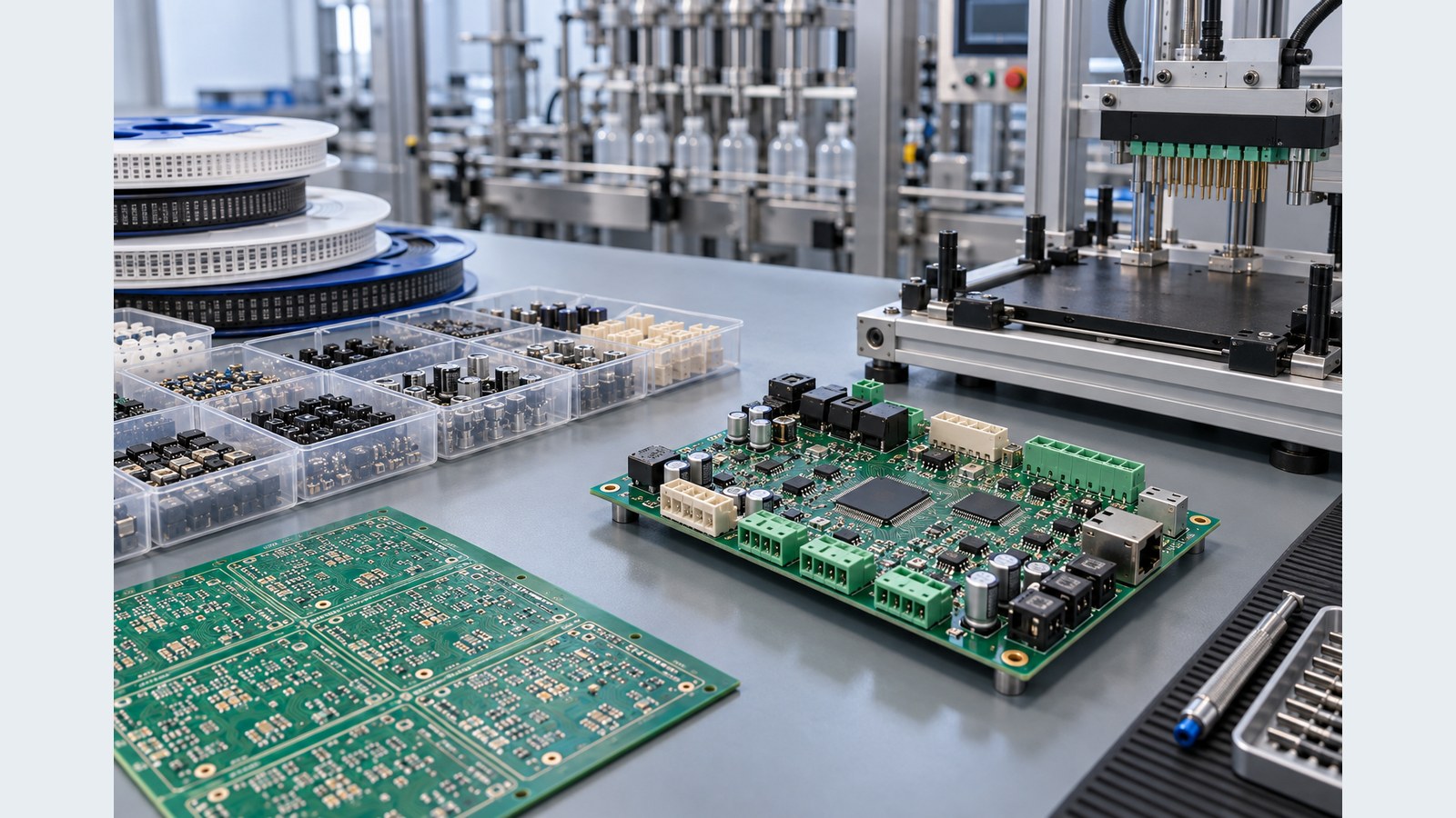
Prototype PCB assembly turns released design data into a small, inspectable PCBA build so engineering teams can validate manufacturability, component choices, assembly instructions and the intended test method before production. OrinewPCB coordinates PCB fabrication, 100% new original component sourcing, SMT/THT assembly and the agreed quality plan through one project team.
A prototype is not simply a smaller production order. It should expose revision conflicts, ambiguous BOM lines, placement errors, soldering risks and missing test instructions early enough to correct them. We review the build package, quantities and target date before confirming price and the earliest practical schedule.
One-stop first build
Coordinate bare boards, approved components, assembly and the defined test plan without splitting revision control across suppliers.
Original component sourcing
Supplier-sourced material is 100% new and original; manufacturer and distributor relationships support price and availability review.
Quality before scale
A nine-step quality workflow records build findings before they become repeat production problems.
Define what the first build must prove
A prototype should validate the released PCBA package, not only power on once
The useful output is a repeatable build baseline: which files were used, which components were fitted, what deviations were accepted, what inspection evidence was generated and which test limits were applied.
Fabrication readiness
Check stackup, board outline, drill data, panel approach and fabrication notes against the assembly drawing. The multilayer PCB design guide explains why stackup decisions should remain tied to released production data.
Assembly readiness
Resolve polarity, rotation, board side, DNP positions, mechanical constraints and mixed SMT/THT routing before the first article becomes the reference build.
Test readiness
Define power-up order, firmware, fixtures, limits and failure disposition. AOI, X-ray, electrical checks and functional testing provide different evidence.
If the project needs a compressed first-build schedule, compare the file and material prerequisites on our quick-turn PCB assembly service page. Speed is confirmed only after the package and components are reviewable.
Release a consistent data set
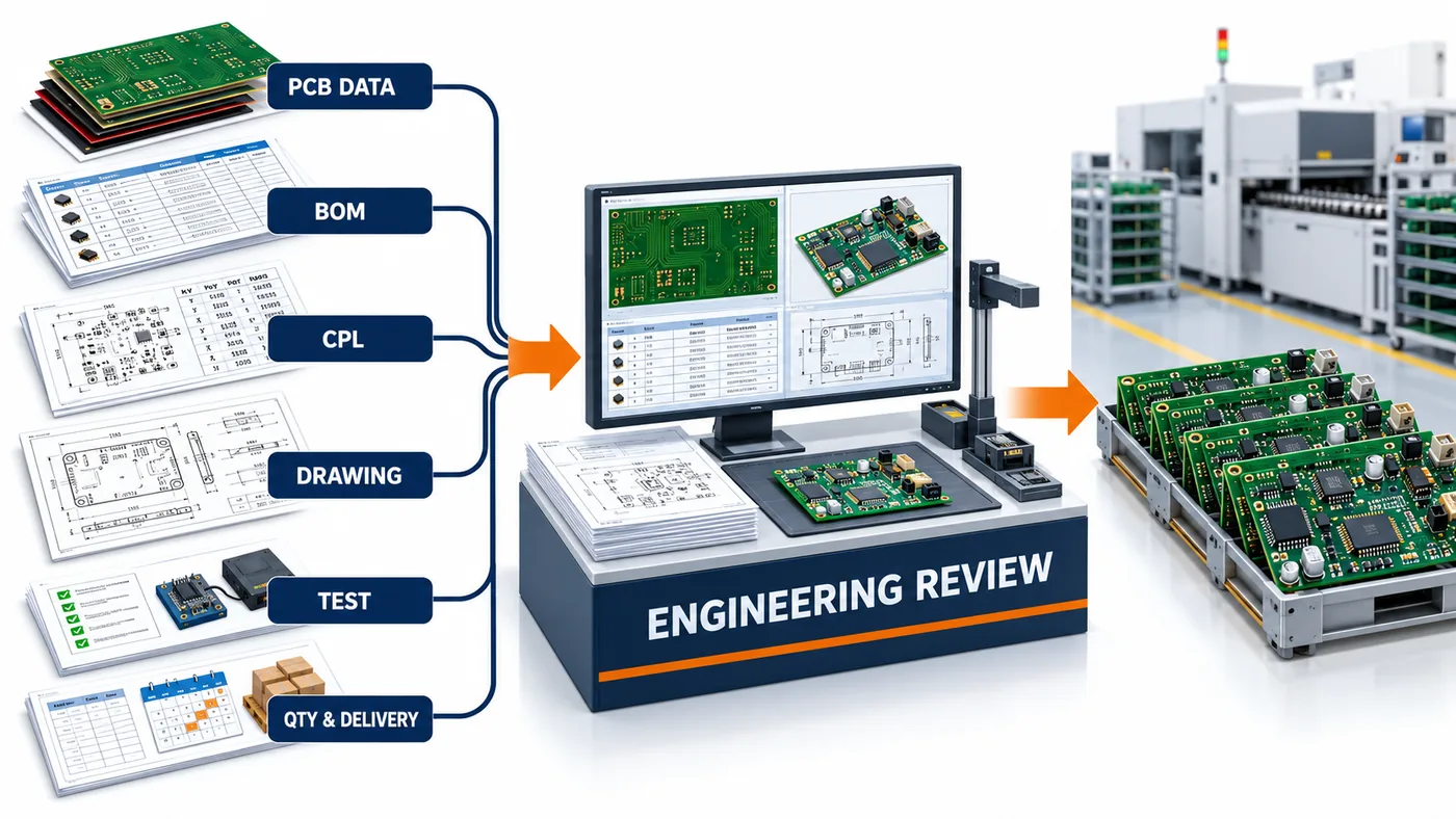
What to send for prototype PCB assembly
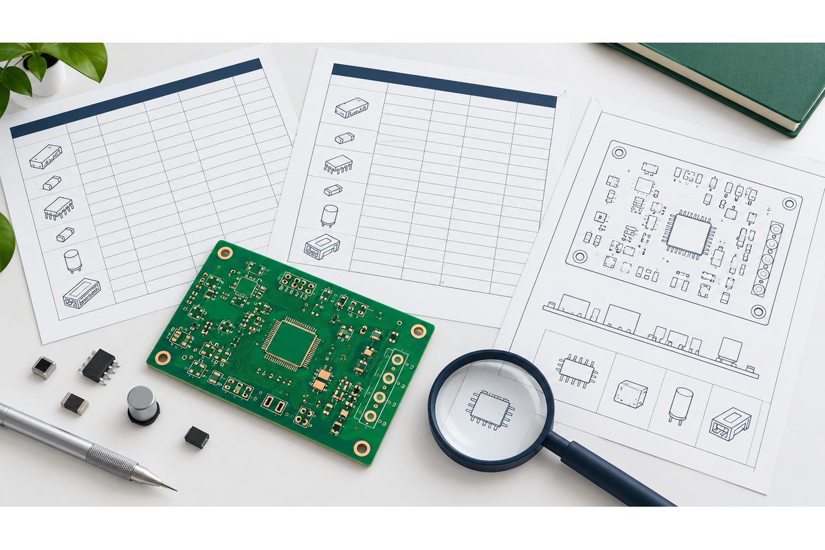
Every file should identify the same PCB and assembly revision. Mark preliminary files clearly and separate each product variant so the wrong BOM or placement program cannot become the build baseline.
| Input | Required detail | Decision it supports |
|---|---|---|
| PCB fabrication data | Gerber or ODB++, drill files, stackup and fabrication drawing | Board construction, revision and manufacturability review |
| BOM | Manufacturer part numbers, references, quantities, DNP lines and approved alternates | Original-part sourcing, shortage and substitution control |
| Placement data | X/Y, rotation, board side, units and origin convention | Program creation and orientation verification |
| Assembly drawing | Polarity, connector orientation, mechanical notes and variants | First-article inspection and operator instructions |
| Test package | Firmware, fixtures, interfaces, safe power-up, limits and disposition | Agreed electrical or functional acceptance scope |
When these files are ready, share the prototype build package for a combined DFM and BOM review. The returned scope can then identify fabrication, sourcing, assembly, inspection and test assumptions together.
Choose the sourcing model deliberately
Full-turnkey prototype assembly lets one team coordinate boards and components. Partial turnkey is useful when the customer controls programmed devices, scarce parts or existing inventory. Consigned assembly can work when the full kit is supplied and receiving responsibilities are clear.
For the responsibility boundary between supplier-sourced and customer-supplied material, review the full and partial turnkey assembly matrix. Any unlisted alternate should remain subject to customer approval.
Quality evidence matched to the design
Inspection and testing must answer a defined prototype question
A prototype quality plan should state what evidence is required and what happens when a result is outside the limit. The nine-step OrinewPCB workflow provides control gates, but not every board needs every inspection technology.
Visible assembly evidence
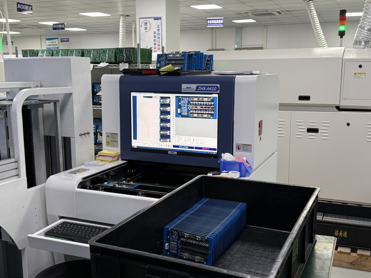
First-article review and AOI can check defined placement, polarity and visible solder features within the method’s capability. The AOI inspection guide explains why programmed optical checks do not replace electrical or functional evidence.
Hidden and electrical evidence
X-ray may be specified for selected hidden joints. Electrical or functional testing requires access, fixtures, firmware and limits. The quotation should name the included evidence instead of using the ambiguous word “tested.”
Close the NPI loop
Move from prototype to small-batch production with a controlled baseline
Do not repeat a prototype from email corrections or remembered rework. Update the PCB revision, BOM, placement file, assembly drawing, approved alternates, programming files and test limits before ordering the next lot.
| Prototype finding | Required production action | Release evidence |
|---|---|---|
| Manual wire or component change | Incorporate it into released design data or document a controlled deviation | Approved ECO or deviation record |
| Alternate component used | Approve it for the affected product and quantity | Updated BOM or written approval |
| Orientation or DNP correction | Align BOM, placement and assembly drawing | Matching file revisions |
| Test limit adjusted | Validate and release the production limit | Controlled test instruction |
OrinewPCB’s one-stop PCB assembly workflow is designed for this transition, especially when several variants or small-to-medium batches need coordinated component sourcing and change control. When the baseline is released, send the files, quantities and test requirements for the next-build review.
Plan the experiment, not just the order
Match the prototype quantity and evidence to the engineering decision
Assembly process proof
A small first article can expose footprint, polarity, stencil, clearances and hand-access issues before the full prototype lot proceeds. Identify the components and interfaces that carry the highest technical risk so the review is not spread evenly across every feature.
Functional learning
If the goal is power-up or firmware validation, define safe current limits, known-good loads, connector pinout, programming method and expected observations. A statement such as “functional test required” is not enough to reproduce the customer’s decision.
Supply-chain learning
A prototype also validates component identity, availability, package choice and alternates. Separate engineering substitutes from production-approved alternates, and record which exact manufacturer part number was installed on each relevant build.
Quantity should cover destructive checks, debug losses, firmware iterations, customer evaluation and retained reference units where applicable. Ordering more boards without a learning plan can increase cost without increasing evidence.
Make high-risk details visible
Common prototype risks to resolve before release
Data conflicts
A BOM may show one package while the placement file and land pattern imply another. Reference designators, polarity marks, DNP status and assembly side must agree. OrinewPCB raises these conflicts for disposition rather than choosing silently.
Parts that cannot be verified or procured
Incomplete manufacturer part numbers, marketplace-only links and ambiguous descriptions slow sourcing. Provide exact MPNs and approved alternates. For supplier-sourced material, the requirement remains 100% new, original components.
Test access discovered too late
Functional coverage may require connectors, cables, fixtures, firmware or test points that are not yet available. Define the practical setup before the board is assembled and distinguish electrical continuity from product-level behavior.
Prototype rework that never reaches the files
A successful hand modification is engineering evidence, not a production baseline. Capture every wire, component change, polarity correction and test-limit change in controlled release data before repeating the build.
Define acceptance at the same time as the risk. For example, specify which rails must power up, what current limit applies, which communication path must respond, and which visible defects are unacceptable. If a test is exploratory, say who will interpret the result and whether boards may be reworked. This keeps a prototype failure useful: the team can distinguish a design finding, a material issue, an assembly process issue and an incomplete test setup. It also lets the quotation include the correct engineering and test effort instead of assuming every assembled board needs identical evidence.
Photographs, serial identifiers and concise result records are most useful when their purpose is decided before the build. Ask for evidence that supports design release, supplier approval or customer evaluation; unnecessary records add handling without improving the decision. The same principle applies to retained samples and failed units: define ownership, disposition and return requirements in advance.
Frequently asked questions
Prototype PCB assembly FAQ
What is prototype PCB assembly?
Prototype PCB assembly is a controlled first build used to validate fabrication data, component choices, placement, soldering, inspection and the intended test approach before a production release.
What files are needed for a prototype PCBA quote?
Send PCB fabrication files, drill data, BOM, centroid or pick-and-place data, assembly drawings, quantities, approved substitution rules and the required programming or test information.
Can OrinewPCB source prototype components?
Yes. OrinewPCB can source 100% new, original components for the approved BOM, or work with customer-supplied and partial-turnkey material when responsibilities are defined in the quotation.
Does every prototype receive the same tests?
No. The nine-step quality workflow defines control gates, while the actual AOI, X-ray, electrical and functional-test scope depends on board design, access, fixtures, software and customer acceptance requirements.
How does a prototype transfer to production?
Close prototype deviations, update the released PCB and BOM revisions, freeze placement and assembly files, document approved alternates and validate the production test limits before ordering the next lot.