
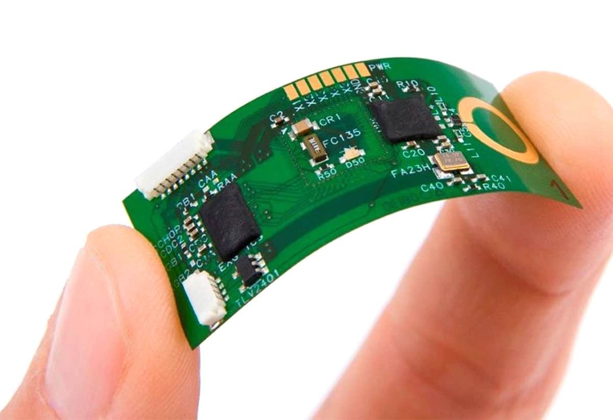

Flex circuits defined by bend region, material stack and assembly boundary
Flexible PCB manufacturing builds a circuit on a thin flexible dielectric so the interconnect can bend, fold or fit a constrained mechanical envelope. A flex PCB should be designed around its actual motion: static installation, limited flex during assembly or repeated dynamic bending. Copper type, bend radius, layer transitions, coverlay, stiffeners, adhesive, connector area and component placement must be coordinated because a board that fits flat may still fail when installed or cycled.
OrinewPCB reviews flexible printed circuit board data and can coordinate fabrication with 100% new and original component sourcing, assembly and project-specific testing. Keeping the flex drawing, BOM, stiffeners, assembly carriers and test fixtures under one controlled project is particularly valuable for small-to-medium batches and multiple mechanical variants.
When should you choose Flexible PCB?
The correct route is the simplest construction that satisfies the released electrical, mechanical, thermal, compliance and assembly requirements. Use the comparison below to define why this board type is necessary before specifying details.
| Route | Use it when | Release decision |
|---|---|---|
| Static flex | The circuit bends mainly during installation and then remains fixed | Define the installed shape, bend area and strain relief |
| Dynamic flex | The circuit moves repeatedly during product operation | Define cycle, radius, direction, copper and environmental conditions |
| Single- or double-layer flex | Routing density and shielding needs remain limited | Control copper, coverlay openings and connector reinforcement |
| Rigid-flex | Rigid component areas and flex interconnects need one integrated structure | Use a dedicated rigid-flex stack and transition review |
Flexible PCB design and DFM controls
The most useful DFM review checks the features that control fabrication and assembly risk, rather than comparing the design with a generic capability list.
Keep features out of the bend zone
Pads, vias, sharp corners and abrupt copper-width changes can concentrate strain. Define the bend region on the drawing.
Select copper for the motion
Rolled-annealed and electrodeposited copper do not provide the same behavior in every flex application; choose against the actual cycle requirement.
Use stiffeners deliberately
Stiffeners support connector, component or contact areas, but their edge and adhesive transition can also create a local stress point.
Plan assembly support
Thin flex circuits may need carriers, tooling features and controlled handling for stencil printing, placement and reflow.
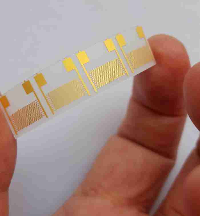
How the manufacturing route is reviewed
A reliable build keeps the requirement, material, fabrication data and acceptance evidence connected through the release process. The exact operations vary with construction, but the following gates should be explicit.
- Mechanical boundary review: Define installed shape, bend radius, cycle and keep-out areas.
- Material and stack approval: Confirm dielectric, copper, coverlay, adhesive and stiffeners.
- Patterning and registration: Create the released flex copper while controlling fine features and layer alignment.
- Coverlay and reinforcement: Apply openings and stiffeners according to the assembly and connector design.
- Profile and handling: Release the outline while protecting thin or irregular flex features.
- Assembly and flex verification: Use the agreed carrier, inspection and bend-related acceptance plan.
Files to send for an engineering review
Every file should identify the same board revision. A complete package shortens clarification time and makes price, material and delivery assumptions visible before production.
| Input | Required detail | Decision supported |
|---|---|---|
| Fabrication data | Gerber, ODB++ or IPC-2581 plus NC drill and board outline | Layer interpretation, holes, profile and DFM review |
| Stackup and materials | Layer order, finished thickness, copper, material and approved-equivalent rules | Construction and material proposal |
| Special requirements | Impedance, mechanical, compliance, finish, marking or documentation needs | Process selection and quotation scope |
| Assembly package | BOM, CPL, assembly drawing, variants and substitution rules when PCBA is required | Original-part sourcing and assembly planning |
| Test and delivery | Acceptance method, required evidence, quantity and target delivery | Inspection, test and schedule basis |
When the release package is ready, share the fabrication files and assembly inputs for a combined engineering review. OrinewPCB can then identify open DFM, material, sourcing and test questions before confirming the quotation scope.
Flexible PCB in one-stop PCB assembly
Flexible PCB assembly adds handling, carrier, paste-printing and mechanical-strain decisions that are not present on a conventional rigid board. The flexible PCB assembly service explains how the flex circuit, stiffeners, original components, tooling and inspection plan can be coordinated for an assembled build.
Compare flexible circuits with rigid-flex PCB manufacturing, review the parent PCB fabrication service, and use turnkey PCB assembly when components and test are included.
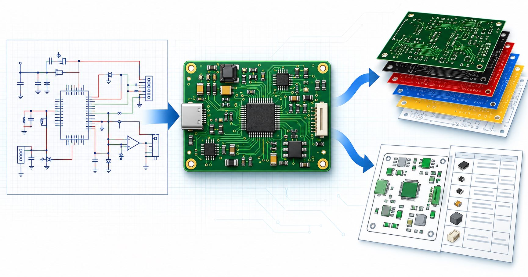
Quality, cost and lead-time factors
OrinewPCB uses a nine-step quality and test control framework that links release review, materials, fabrication, assembly and final verification. The actual inspection and test methods are selected for the board and customer-defined acceptance scope; not every board needs every method.
Flexible PCB cost is influenced by panel utilization, outline shape, material, copper type, layer count, coverlay openings, stiffeners, adhesive, testing and assembly carriers. Mechanical definitions provided early reduce quotation assumptions and avoid late tooling changes.
- Resolve missing or conflicting data before material is committed.
- Keep approved substitutions and evidence requirements in the released order.
- Confirm panel, tooling and assembly constraints together when PCBA is included.
- Plan delivery as early as practical after material, process and test inputs are reviewed.
Flexible PCB FAQ
What is a flexible PCB?
A flexible PCB is a printed circuit built on a flexible dielectric so it can bend or fold within a defined mechanical envelope.
What is the difference between static and dynamic flex?
Static flex is mainly bent during installation; dynamic flex is repeatedly cycled in operation and needs a more demanding mechanical definition.
What files are needed for flexible PCB manufacturing?
Provide fabrication data, stackup, outline, bend regions, material, coverlay openings, stiffeners, quantity and the required electrical or mechanical acceptance criteria.
Can components be assembled on a flex PCB?
Yes. The assembly route should define carriers, tooling, component support, inspection and the installed mechanical condition.
Plan the next build from one controlled data set
The board construction, component BOM, assembly revision and acceptance plan should describe the same product. This reduces supplier handoffs and makes engineering decisions easier to trace across prototypes, small-to-medium batches and high-mix production.
If the project is ready to move forward, provide the released PCB data, BOM, quantities and test requirements for the next-build review. The returned scope can address fabrication, 100% new and original component sourcing, assembly, testing and the earliest practical delivery plan together.