
OrinewPCB · From build data to assembled boards
Automated PCB Assembly Services
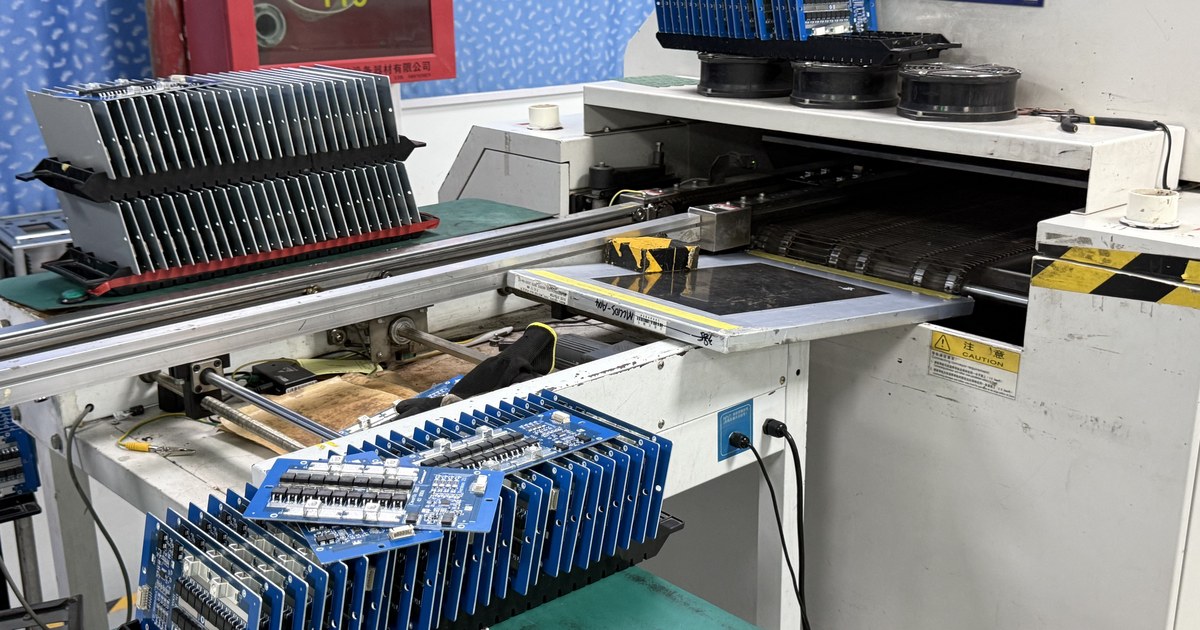
Automated PCB assembly uses programmed equipment for repeatable operations such as component placement and inspection. OrinewPCB combines automated assembly with PCB fabrication, 100% new original components and agreed testing for high-mix, low- and medium-volume projects.
Send one design or several board variants. Our team reviews the BOM, placement data, assembly drawings, test requirements and target date before confirming the complete quotation and earliest practical delivery schedule.
- High-mix, small-batch focus
- 100% new original parts
- Nine-step quality workflow

One team for the complete PCBA
Coordinate board fabrication, components, assembly, inspection and testing within one project.
Original parts and sourcing value
Deep cooperation with manufacturers and distributors supports genuine components, competitive material prices and availability.
Quality and delivery planned together
Our nine-step quality workflow and your acceptance requirements inform the production schedule.
Why choose PCB assembly automation?
Repeatability matters, even when the order is a small batch
Automation can improve consistency in repetitive operations. Its value depends on accurate build data, suitable components, correct setup and the order quantity—not simply whether a machine is involved.
Repeatable placement
Programmed placement can position many surface-mount parts consistently when the component data, feeder setup, board orientation and machine program are correct.
Coordinated inspection
Inspection programs can check defined assembly features repeatedly. Results still need appropriate review, acceptance criteria and a controlled response to suspected defects.
Planned variant changeovers
Multiple models need the correct program, BOM and work instructions at each changeover. Shared components may help preparation, but variant differences must remain explicit.
Automated handling can reduce some repetitive manual work, while setup, replenishment, maintenance and process supervision remain necessary. Automation does not make a line error-free or remove the need for operator safety controls.
Define the assembly route
Which PCB operations can be automated?
A practical build often combines automated and manual operations. Component packages, board access, thermal limits and test requirements determine the appropriate route; not every order needs every method below.
| Operation | Role of automation | What needs review |
|---|---|---|
| Paste printing and inspection | Apply solder paste to the required pads and inspect deposits where specified. | Stencil design, pad geometry, paste condition and inspection scope. |
| Component placement | Place surface-mount components using the released program and component data. | Feeder packaging, polarity, board side, coordinates and component compatibility. |
| Reflow soldering | Move assemblies through a controlled thermal process. | Actual board thermal behavior, paste guidance and component limits. |
| Optical inspection | Inspect accessible assembly features against programmed criteria. | Coverage, false calls, defect review and reinspection requirements. |
| Electrical or functional testing | Execute agreed checks with suitable programs, access and fixtures. | Test coverage, firmware, interfaces, pass/fail limits and records. |
| Manual or through-hole work | Complete operations that need a different process or direct access. | Insertion, soldering route, special handling and mixed-assembly sequencing. |
For placement and soldering detail, see our SMT assembly service. Boards with leaded connectors or other through-hole parts may also require THT assembly planning.
High-mix production readiness
Release one consistent file set for each board variant
A machine can repeat an incorrect instruction as consistently as a correct one. Match the BOM, placement file and drawings to the released PCB revision before setup, and document differences between product variants.
| Input | What to include | Problem it helps prevent |
|---|---|---|
| PCB fabrication files | Gerbers, drill files, stack-up and released fabrication notes. | Using a board revision that does not match the assembly data. |
| BOM | Manufacturer part numbers, reference designators, quantities, DNP positions and approved alternatives. | Incorrect parts, ambiguous substitutions and variant mix-ups. |
| Placement / CPL data | Reference designator, X/Y coordinates, rotation, board side, units and origin convention. | Wrong board side, coordinate interpretation or orientation. |
| Assembly drawing | Polarity, mechanical orientation, connector requirements and special handling notes. | Assuming placement data alone describes every assembly requirement. |
| Variant and test definition | Quantity and revision for each model, component changes, firmware and acceptance criteria. | Loading the wrong configuration or testing against the wrong limits. |
Show critical orientation details on the drawing even when rotation values are supplied. Coordinate conventions and package orientation should be reconciled during preparation rather than assumed to be identical across software tools.
For general industry context, Yamaha’s SMT production software overview describes program and setup planning across printer, placement and inspection equipment. These are equipment-platform features, not a specification of every OrinewPCB production line.
If the BOM, placement data, Gerbers and test requirements are ready, share the controlled build package for engineering review so fabrication, sourcing, assembly and testing assumptions can be checked together.
A controlled production sequence
From file review to an accepted assembly
Good automated assembly links engineering preparation, verified setup and defined acceptance. OrinewPCB reviews the complete project so the automated stages and any additional work are coordinated.
-
Review files and the complete BOM
Confirm revisions, component availability, placement data, quantities and manufacturing questions. Resolve substitutions and variant differences before releasing the production package.
-
Prepare materials and the line
Review material handling, component packaging, stencils, programs and required fixtures. Define how the correct materials and instructions are selected for each model.
-
Verify setup and the initial assembly
Check orientation, part identity and the assembled result before continuing the batch. Resolve discrepancies and update the controlled instructions where necessary.
-
Assemble and inspect
Carry out the reviewed printing, placement, soldering and inspection route. Include through-hole or manual operations where the design requires them.
-
Test and prepare delivery
Complete the agreed programming, electrical or functional tests and acceptance checks. Confirm packing and shipment requirements for the released quantity and variants.
Original materials · Defined test coverage
A nine-step quality workflow, with checks matched to the design
OrinewPCB uses 100% brand-new original components and emphasizes quality through a nine-step inspection and testing workflow. Applicable methods, acceptance criteria and reporting requirements are agreed for the project.
Authentic component supply
Deep cooperation with manufacturers and distributors supports original electronic components, competitive BOM pricing and practical material lead times. Approved alternatives must be identified before use.
Controlled setup and changes
Each model needs matching material, program and drawing revisions. Highlight DNP positions, firmware differences and late changes so they can be reviewed against the correct build.
Acceptance before shipment
Define the functions, electrical checks, programming and records your product needs. Quality scope and delivery planning should be agreed together.
| Method | What it addresses | What it does not establish by itself |
|---|---|---|
| Solder paste inspection (SPI) | Specified deposit characteristics before component placement. | Finished solder-joint condition or circuit operation. |
| Automated optical inspection (AOI) | Accessible component and solder features within the inspection program. | Hidden-joint integrity or complete electrical function. |
| X-ray inspection, where specified | Selected hidden solder-joint features and internal geometry. | Full functional performance or every possible defect. |
| Electrical testing | Defined electrical characteristics, depending on test access and method. | All behavior under the product’s operating conditions. |
| Functional testing | Operation under specified inputs, power, loads and firmware. | Complete lifetime reliability or performance outside the defined test conditions. |
These methods serve different purposes and are not a substitute list for the nine-step workflow. Our AOI guide explains why optical inspection and electrical testing need distinct roles in an assembly quality plan.
A complete cost comparison
What affects automated PCB assembly cost?
Price depends on the full build scope, including components, PCB fabrication, setup, assembly and testing. A generic per-board price range cannot account for the difference between a simple board and a complex, multi-variant project.
- BOM value, availability and approved component alternatives.
- Component count, package mix, board sides and special handling.
- Stencil, programming, fixture and setup effort.
- Quantity per model, changeovers and repeat-order preparation.
- Inspection, firmware programming, test execution and reporting.
Our sourcing relationships help improve material pricing and availability. Compare quotations using the same BOM revision and acceptance scope so the total project cost is meaningful.
The earliest practical delivery
What determines lead time?
Machine placement time is only one part of delivery. File approval, original component readiness, PCB completion, setup and agreed testing all affect the schedule.
- Provide a clear revision and quantity for each variant.
- Identify long-lead parts and substitution rules early.
- Release test procedures and firmware before setup.
- Include the target delivery date with the initial inquiry.
We work toward a fast practical schedule while retaining the agreed quality requirements. For urgent builds, review our quick-turn project requirements with the full material and assembly scope.
One package · One-stop PCBA review
Prepare your automated assembly inquiry
Send the available files for one design or multiple models. OrinewPCB reviews fabrication, original component supply, assembly, inspection and testing, total cost and delivery together.
- Board data: Gerbers, drill files, stack-up and fabrication requirements.
- BOM: part numbers, references, quantities, DNP positions and substitution rules.
- Assembly data: placement/CPL file, board-side information, orientation and drawings.
- Order and acceptance: quantities by variant, revisions, firmware, test requirements and target date.
If you are ready to compare the complete build scope, provide the released PCB, BOM, placement, quantity and test requirements so the project team can review the quotation scope and earliest practical schedule.

Automated PCB assembly FAQ
Questions before a production order
Can PCB design be automated?
Electronic design tools can automate tasks such as rule checking and some routing operations. This is separate from manufacturing automation, and it does not replace engineering review of the schematic, layout, fabrication and assembly requirements.
How much does automated PCB assembly cost?
A firm quotation needs the BOM, board data, placement file, drawings, quantities and test requirements. Setup and materials can be a significant share of a small order, so a universal per-board price would be misleading.
What is an automated PCB drilling machine?
It is equipment used during bare-board fabrication to create specified holes. Drilling is separate from component placement and soldering; it does not verify assembled solder joints or product function.
Is automated assembly suitable for low-volume projects?
It can be, depending on component mix, setup effort, quantity and verification requirements. OrinewPCB focuses on high-mix, low- and medium-volume one-stop PCBA and reviews the appropriate route for the project.
Does automation remove all manual assembly work?
No. Some connectors, through-hole components, mechanical operations or special handling steps may require manual work or a different assembly process. The actual route is reviewed from the complete BOM and drawings.
Does AOI guarantee that the board will function?
No. AOI checks specified visible features. Electrical or functional testing needs its own coverage, access, test conditions and acceptance limits.
Related assembly methods