
OrinewPCB · Through-hole technology
Through-Hole PCB Assembly Services
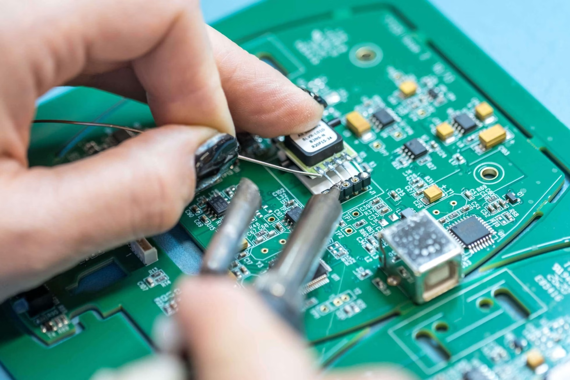
Through-hole technology (THT) inserts component leads into PCB holes and solders them to the board. OrinewPCB combines THT and mixed SMT/THT assembly with PCB fabrication, 100% new original components and agreed testing for high-mix, low- and medium-volume projects.
Send your BOM, assembly drawings and quantity by variant. Our team reviews the complete build, quality requirements and target date before confirming pricing and the fastest practical delivery schedule.
- High-mix, small-batch focus
- 100% new original parts
- Nine-step quality workflow

One project, one assembly partner
Coordinate PCB fabrication, component sourcing, SMT/THT assembly and testing through one team.
Original parts, competitive BOM cost
Deep cooperation with manufacturers and distributors supports genuine materials, favorable pricing and component availability.
Quality planned before production
Our nine-step quality workflow and your acceptance requirements inform the build and delivery plan.
What is through-hole PCB assembly?
THT for leaded parts, connectors and serviceable assemblies
THT is useful when a design requires leaded components or mechanically supported connections. Reliability depends on the component, PCB design, soldering process and operating conditions; THT is not automatically the best choice for every circuit.
Connectors and mechanical loading
Leaded connectors, terminal blocks and other parts can transfer insertion or handling loads into the board. Confirm retention, mounting hardware and the enclosure interface rather than relying only on solder joints.
Power and larger components
Some transformers, relays, capacitors and power components use through-hole packages. Their thermal mass, spacing and mounting instructions influence soldering access and the process plan.
Prototypes and repair access
Accessible leads can help with inspection and component replacement. Rework still requires controlled heat and handling to avoid lifting pads or damaging plated holes.
Many products combine leaded components with surface mount PCB assembly. For those projects, review the entire board and assembly sequence together rather than treating THT as an isolated final operation.
Process selection
Hand, wave or selective soldering: what should you compare?
The appropriate soldering route depends on board population, access, thermal limits, quantity and fixture needs. The table explains general process choices; the method for your order is confirmed during engineering review.
| Method | Typical use | Main review points |
|---|---|---|
| Controlled hand soldering | Prototypes, small quantities or individual joints needing direct access. | Operator access, consistent work instructions, heat exposure and joint inspection; labor rises with joint count. |
| Wave soldering | Boards with a suitable population of through-hole joints and an accessible solder side. | Component compatibility, underside protection, pallet needs, thermal mass and solder bridging risks. |
| Selective soldering | Localized THT joints on mixed-technology boards where surrounding parts need protection. | Nozzle access, clearances, program and fixture needs, plus the quantity needed to justify setup. |
Temperature and exposure limits are component- and assembly-specific. Texas Instruments’ handling and process recommendations explain why example wave profiles need adjustment for the actual board and materials. We do not apply a universal temperature recipe to every build.
From released files to finished boards
Plan the THT assembly sequence before soldering
A repeatable through-hole build starts with complete drawings and a controlled BOM. The soldering and inspection route should account for both leaded parts and any SMT components already on the board.
-
Review the design and materials
Check PCB revision, finished hole requirements, lead dimensions, orientation, polarity and component thermal guidance. Resolve unclear substitutions and drawing conflicts before setup.
-
Prepare and insert components
Define lead forming, insertion depth, component standoff and retention from the assembly instructions. Identify parts requiring mechanical support or special handling.
-
Solder with a reviewed process
Choose the applicable hand, wave or selective route. Review access, heat-sensitive parts and any solder pallet or fixture requirements before confirming production.
-
Inspect joints and resolve defects
Inspect placement, polarity, wetting, bridging and solder fill against the agreed criteria. Any rework needs a controlled method and subsequent reinspection.
-
Test, accept and prepare shipment
Carry out the agreed electrical or functional checks, programming and acceptance activities. Confirm packing and delivery requirements with the completed assembly scope.
Why partner with OrinewPCB?
Original components and a nine-step quality workflow
OrinewPCB uses 100% brand-new original components and emphasizes quality through a nine-step inspection and testing workflow. Applicable methods, acceptance criteria and reporting requirements are confirmed for the actual project.
Authentic materials
Manufacturer and distributor relationships support original electronic component sourcing, competitive BOM pricing and practical lead times. Specify approved manufacturer part numbers and alternatives.
Multiple variants, controlled revisions
We focus on high-mix, low- and medium-volume PCBA. Identify quantity, revision, DNP positions and component differences for each model so the build package can be checked consistently.
Quality and schedule together
We work toward the earliest practical delivery date while retaining the agreed quality scope. Material readiness, fixtures and testing are reviewed before the schedule is confirmed.
| Checkpoint | What it addresses | What to specify |
|---|---|---|
| Placement and joint inspection | Incorrect parts or polarity, visible solder defects and assembly condition. | Assembly drawings, component orientation, joint acceptance criteria and inspection access. |
| Electrical testing | Defined connection or circuit-level electrical checks; coverage depends on test access and the chosen method. | Accessible test points, net or circuit requirements, limits and any required fixture. |
| Functional testing | Operation of the assembly under defined power, input and load conditions. | Firmware, procedure, interfaces, fixtures and explicit pass/fail limits. |
| Rework and final acceptance | Verification that corrected assemblies meet the agreed requirements. | Reinspection, retest, records and packaging requirements. |
These are planning categories, not a replacement list for the nine-step workflow. Visual inspection does not establish functional performance, and no single test provides complete coverage of every possible defect.
Assembly readiness
Resolve these design questions before the quotation is finalized
Finished holes, lead geometry and access can change the assembly route and fixture cost. Provide the actual component data and board revision rather than relying on a nominal drill size alone.
| Design input | What to review | Why it matters |
|---|---|---|
| Finished holes and leads | Finished hole dimensions and tolerances versus the maximum lead geometry and fabrication requirements. | Supports insertion and soldering without guessing a universal clearance. |
| Thermal connections | Large copper areas, plane connections, component thermal limits and soldering access. | Helps define heat input and avoid an unsuitable generic profile. |
| Mechanical fit | Connector mating, board edges, standoffs, lead protrusion and enclosure constraints. | Prevents an electrically correct board from failing mechanical assembly. |
| Underside population | SMT parts, keep-outs and access for the proposed soldering process or fixture. | Determines protection, clearance and process feasibility for mixed builds. |
Review these inputs alongside the PCB fabrication requirements. Where the component drawing and PCB notes disagree, resolve the released specification before manufacturing starts.
A complete cost review
What affects THT assembly pricing?
Assembly cost depends on the BOM, number and accessibility of joints, process setup, variants, fixtures and test scope. Board area alone does not define a through-hole assembly price.
- Component availability, approved alternatives and supply constraints.
- Insertion and soldering work per board, including special handling.
- Setup and fixture costs shared across the order quantity.
- Inspection, programming, functional testing and reporting requirements.
Our sourcing relationships help improve material cost and availability. The quotation identifies the actual scope rather than promising the same price for every design.
The fastest practical schedule
What determines delivery time?
Lead time combines file approval, PCB fabrication, component readiness, assembly, testing and shipment. THT is only one part of that schedule.
- Supply the quantity and approved revision for every variant.
- Flag long-lead components and substitution rules early.
- Confirm fixtures, programming and test procedures before setup.
- Include your required delivery date with the first inquiry.
For urgent work, review the quick-turn project requirements with our team. Delivery is confirmed after the design and material checks.
One-stop PCB assembly inquiry
Send one package for the complete PCBA review
Whether you need a small THT batch or several SMT/THT variants, provide the available files. OrinewPCB will review fabrication, original component supply, assembly, testing, pricing and the target delivery date together.
- PCB data: Gerbers, drill files and fabrication notes.
- BOM: manufacturer part numbers, quantities and substitution rules.
- Assembly data: drawings, polarity, lead/standoff details, DNP positions and SMT placement data when applicable.
- Project scope: quantity and revision by model, test requirements, firmware and target date.
THT assembly FAQ
Questions before a through-hole assembly order
Can you combine THT and SMT on the same board?
Yes, subject to design review. Provide the complete BOM, drawings and SMT placement data so the soldering sequence, access and thermal constraints can be checked together.
Do you accept small batches and multiple models?
High-mix, low- and medium-volume one-stop PCBA is a core focus. List the quantity, revision and differences for each model; the quote will account for setup and any fixture requirements.
Is through-hole assembly always more reliable than SMT?
No. Through-hole mounting can suit leaded components and some mechanical loads, but product reliability depends on the full design, component selection, assembly process and operating environment.
Can I get a firm price from a bare-board image?
An image helps explain the project, but a firm assembly scope needs the BOM, PCB data, drawings, quantities and test requirements. Send what you have and identify which files are still being finalized.
Assembly methods