LED PCB Board Manufacturing
OrinewPCB provides custom LED PCB board manufacturing for lighting, signage and industrial products, including aluminum and other thermally managed constructions. Add 100% new and original LEDs and components, one-stop assembly and project-defined testing when your build requires PCBA delivery.
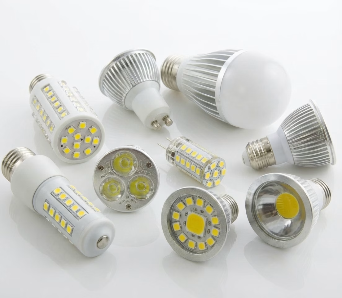
14+
Years Experience
98.15%
On-Time Delivery
96%
customer satisfaction rate
99%
Quality Pass Rate
Our LED PCB Customization Capabilities
Thermal-path, optical-layout and assembly decisions connected before production
An LED PCB board supports and electrically connects LEDs while helping move heat away from the LED junction through pads, copper, dielectric, vias and the final heat-sink interface. The correct LED circuit board is not automatically aluminum: FR-4, aluminum metal-core PCB, copper-core, ceramic, flexible and rigid-flex constructions can each be appropriate when the power density, board shape, insulation, weight, optics, cost and assembly process justify them. The design should therefore begin with LED package data, current, expected losses, allowable temperatures, mechanical interface and lifetime target.
OrinewPCB can review custom LED PCB manufacturing data and coordinate the bare board with 100% new and original LEDs, drivers and supporting components, assembly and project-specific testing. For prototypes, small-to-medium batches and high-mix lighting products, one controlled project keeps board material, LED bin or MPN, polarity, thermal interface, optics, driver requirements and test limits aligned. The dedicated LED PCB assembly page remains the primary resource for placement and soldering; this page focuses on selecting and manufacturing the LED PCB itself.
Choose the board route from the actual application
The simplest suitable construction is usually easier to control than a more complex board selected from an application label. The following comparison turns the product requirement into a release decision.
| Route | Use it when | Release decision |
|---|---|---|
| FR-4 LED PCB | Power density is moderate and cost, multilayer routing or integrated control circuitry dominates | Copper area, thermal vias, layer stack and heat-sink interface |
| Aluminum LED PCB / MCPCB | A metal base and dielectric thermal path provide a practical route for planar lighting boards | Base metal, dielectric, copper, isolation and finished thickness |
| Copper-core or advanced thermal PCB | Heat flux, current or geometry requires more thermal performance than the approved aluminum route | Material system, isolation, mass, machining and assembly profile |
| Flexible LED circuit board | The lighting surface must bend or fit a curved, narrow or weight-sensitive envelope | Bend region, copper, coverlay, stiffeners and thermal attachment |
| Rigid-flex or mixed construction | Control circuitry and shaped light sections need an integrated interconnect | Transition design, panel support, folding and assembly sequence |
LED PCB Board Manufacturing: design and DFM controls
A useful DFM review focuses on the electrical, thermal, mechanical and sourcing facts that can change fabrication or assembly. It should not rely on a generic capability list.
Build a complete junction-to-ambient thermal path
Board conductivity alone does not establish LED temperature. Include LED thermal resistance, pad design, copper spreading, dielectric, base plate, interface material, heat sink and airflow in the review.
Choose material from heat and isolation requirements
For an aluminum LED PCB, specify base metal, dielectric electrical strength, thermal property requirement, copper weight and finished thickness instead of requesting generic aluminum.
Coordinate LED package, polarity and optical datum
Exact LED MPN, footprint, pin-1 or cathode marking, orientation, spacing, lens or reflector clearances and board datum should agree across the BOM, CPL and drawing.
Control large copper and solder-volume effects
Thermal pads and copper spreading can pull heat during reflow. Stencil apertures, via-in-pad treatment and solder profile must be planned with the assembly route.
Plan mounting and surface finish
Board flatness, screw holes, slots, edge features, white mask or other optical surfaces, finish and interface pressure can affect assembly and the final thermal contact.
How the manufacturing and assembly route is controlled
A reliable build connects product requirements, PCB data, component identity, assembly instructions and acceptance evidence. Each gate below should close against one released revision.
- Thermal and optical inputs: Confirm LED package, current, losses, target temperature, board geometry and optical constraints.
- Construction selection: Choose FR-4, aluminum/MCPCB, copper-core, flex or another route from the released requirements.
- PCB DFM review: Resolve copper, dielectric, isolation, thermal vias, outline, mounting, finish and panel design.
- Fabrication: Build the approved stack and complete the agreed electrical, dimensional and visual checks.
- Assembly coordination: Align paste, placement, polarity, thermal mass, fixtures and reflow with the LED board.
- Verification: Apply the customer-defined electrical, light-output, programming or thermal checks to the correct revision.
Files to send for an engineering review
Complete inputs shorten clarification time and prevent assumptions from becoming purchasing or production commitments. Every file should carry the same board, BOM and variant revision.
| Input | Required detail | Decision supported |
|---|---|---|
| PCB data | Gerber/ODB++, drill, outline, stackup, copper and material specification | LED PCB fabrication and DFM |
| LED and BOM data | Exact LED/driver MPNs, approved alternates, bins where applicable and component ratings | Sourcing and electrical planning |
| Assembly data | CPL, drawings, polarity, thermal-pad treatment, variants and stencil notes | Placement, paste and reflow |
| Thermal inputs | LED power/loss assumptions, allowable temperatures, interface material, heat sink and airflow | Construction and thermal-path review |
| Mechanical/optical | Enclosure, mounting, lens/reflector clearance, datum, flatness and surface requirements | Fit and optical alignment |
| Test and delivery | Quantity, variant mix, target date, programming and pass/fail criteria | Quotation and release plan |
When the package is ready, send the PCB files, BOM, quantities and acceptance requirements for a combined engineering review. OrinewPCB can identify open construction, sourcing, assembly and test questions before confirming the quotation scope.
One-stop component sourcing and PCB assembly
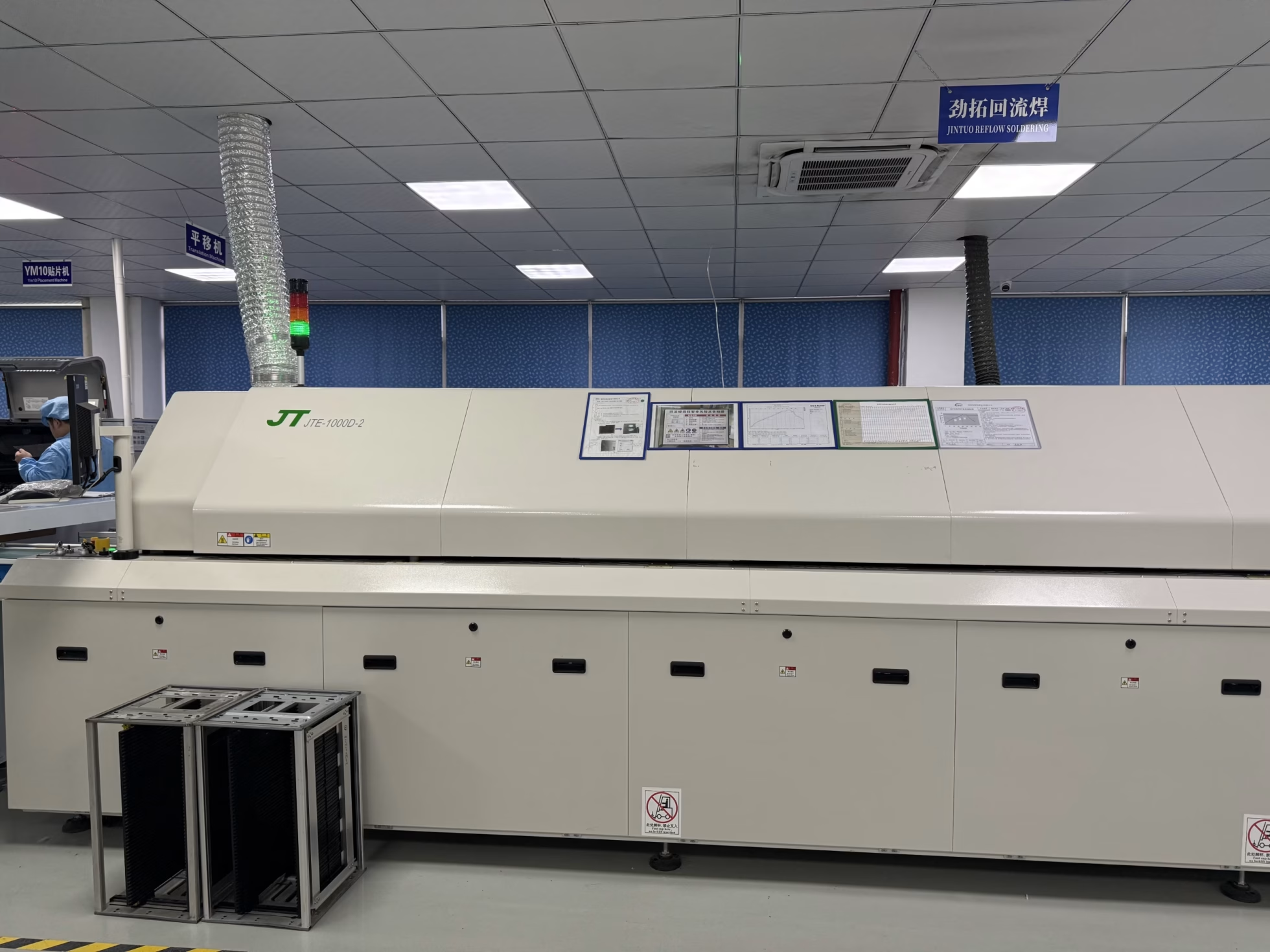
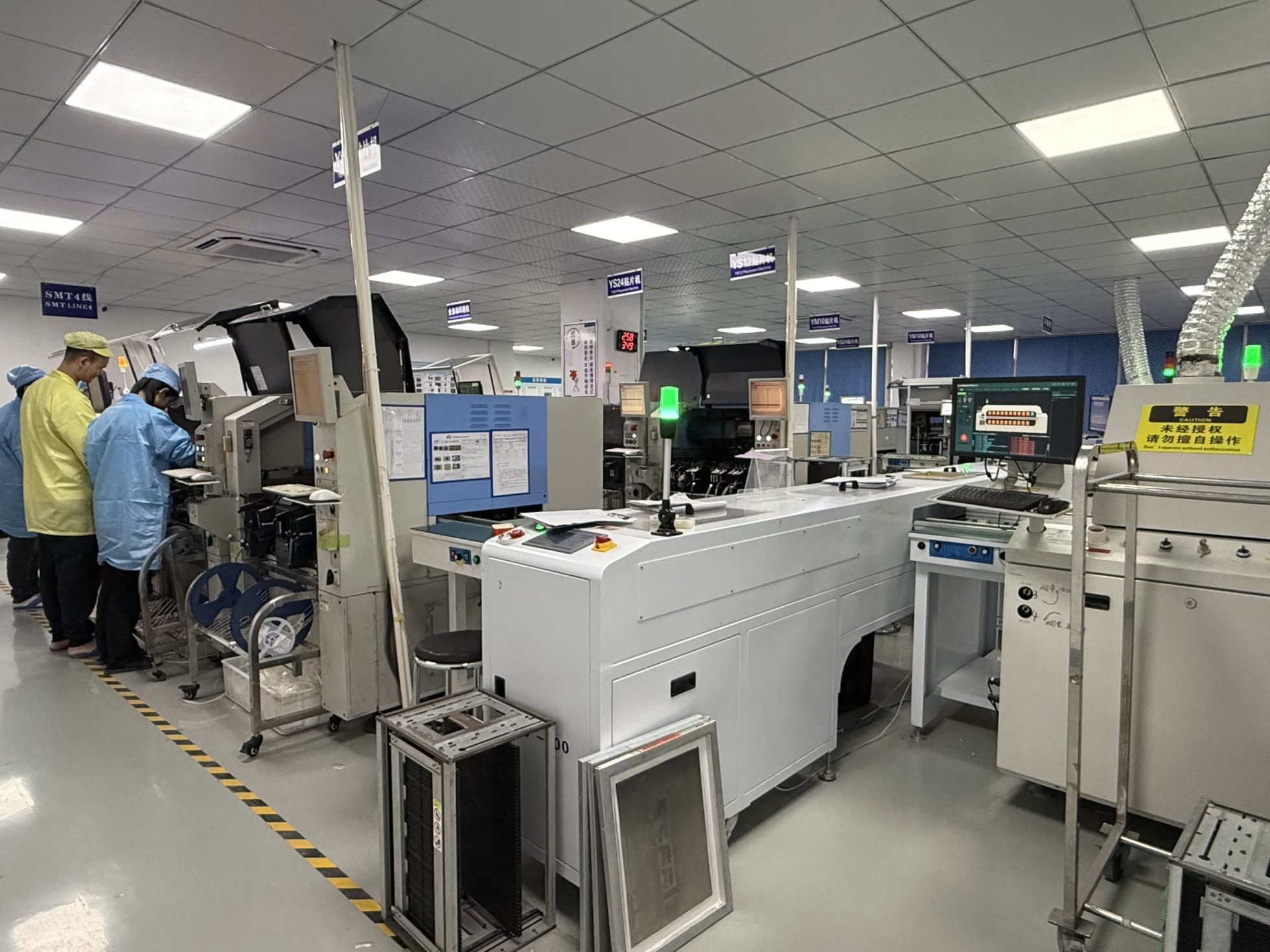
An LED PCB can be manufacturable as a bare board yet difficult to assemble when thermal pads, large copper areas, polarity markings, mixed component heights or optics are not coordinated. For the placement, soldering and inspection process, use the LED PCB assembly service. A broader turnkey PCB assembly scope can combine the custom LED PCB, original LEDs and drivers, other components and customer-defined verification under one revision.
Compare the material decision with high-Tg PCB planning where assembly heat or service temperature needs more margin, and review the parent PCB manufacturing service for the complete fabrication input set.
Quality and test planning must match the released product
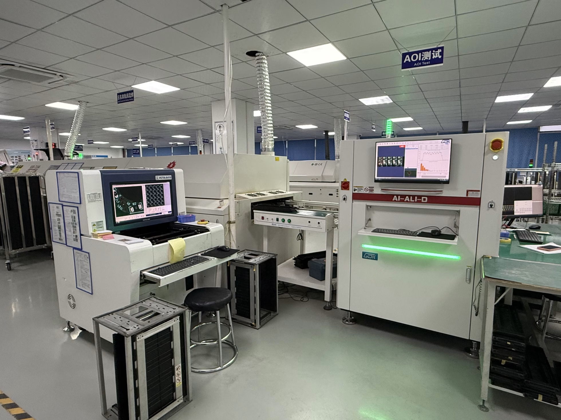
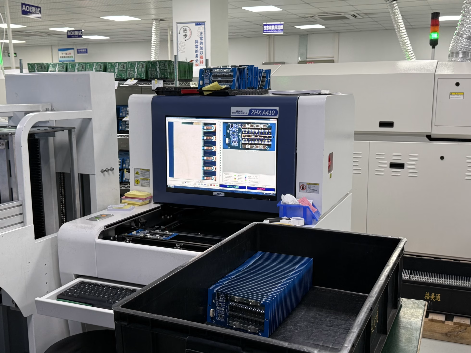
OrinewPCB uses a nine-step quality and test workflow that connects release review, materials, fabrication, assembly and final verification. For an LED PCBA, the agreed plan may include board electrical test, polarity and placement checks, AOI, controlled power-up, current or voltage checks, programming and customer-defined light-output or thermal verification. The page does not substitute a generic test list for the product’s actual acceptance conditions.
- Resolve conflicting PCB, BOM, placement and drawing revisions before materials are committed.
- Record approved component alternates and the engineering conditions attached to each substitution.
- Define the inspection, programming and functional evidence that will be delivered with the build.
- Return accepted deviations and rework findings to the next controlled release.
Cost and lead-time factors
LED PCB board cost and lead time depend on material system, board size, panel utilization, copper, dielectric, isolation, machining, finish, LED availability, assembly tooling and test preparation. Aluminum LED PCB can be cost-effective for many lighting designs, but it should not be specified when a properly designed FR-4 route meets the thermal requirement. Early thermal and sourcing review reduces late changes to material, LED footprint or heat-sink geometry.
OrinewPCB works with manufacturers and authorized or established distribution channels to support component pricing and material schedules, while maintaining the stated requirement for 100% new and original parts. Delivery is planned for the earliest practical date after construction, material, assembly and test inputs are confirmed.
LED PCB PCB FAQ
What is an LED PCB board?
It is a circuit board that supports and connects LEDs and contributes to the thermal path from the LED package toward the final heat-spreading and cooling structure.
Does every LED circuit board need an aluminum base?
No. FR-4, aluminum, copper-core, ceramic, flex and rigid-flex constructions can be appropriate. Select the board from the released electrical, thermal, mechanical and cost requirements.
What data is needed for custom LED PCB manufacturing?
Provide PCB files, stackup and material requirements, exact LED and driver MPNs, current and thermal inputs, mechanical/optical drawings, quantities and acceptance criteria.
Can the LED PCB be supplied as an assembled board?
Yes. The board can continue into original component sourcing, LED placement, soldering, inspection and the customer-defined electrical, programming, light-output or thermal checks.
Plan the next build from one controlled data set
The PCB construction, component BOM, placement revision, product interfaces and acceptance criteria should describe the same deliverable. That alignment is especially important for prototypes, small-to-medium batches and high-mix programs where several variants may share similar files.
If the design is ready for review, provide the released manufacturing data and project requirements for the next-build assessment. The returned scope can address PCB fabrication, original component sourcing, assembly, project-defined testing and the earliest practical delivery plan together.
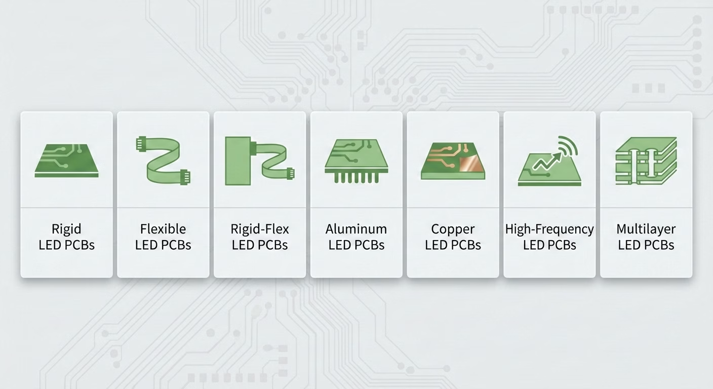
Rigid LED PCBs
Rigid LED PCBs are built from FR-4 material, providing strong structural support for applications where bending is not required. These are commonly used in lighting fixtures, automotive lighting, and electronic devices, offering high-density component placement and reliable performance.
Flexible LED PCBs
Flexible LED PCBs utilize bendable materials, making them ideal for wearable devices, LED strips, and curved lighting where space constraints demand adaptability. Their design versatility allows seamless integration into compact or irregularly shaped products.
Rigid-Flex LED PCBs
Rigid-Flex LED PCBs combine both rigid and flexible layers, making them suitable for medical devices, aerospace applications, and high-end consumer electronics. By reducing interconnects, they save space and improve reliability, especially in dynamic environments.
Aluminum LED PCBs
Aluminum LED PCBs feature an aluminum base layer, enhancing heat dissipation for high-power LED applications such as automotive headlights, industrial lighting, and high-intensity illumination systems. This material extends the lifespan and efficiency of LEDs by preventing overheating.
Copper LED PCBs
Copper LED PCBs offer even higher thermal conductivity than aluminum, making them ideal for high-performance, high-power LED applications that demand superior heat management. These are commonly used in advanced industrial and high-output lighting systems.
High-Frequency LED PCBs
High-Frequency LED PCBs are designed for communication devices and high-speed electronics where minimizing signal loss is critical. These boards ensure signal integrity and reduce electromagnetic interference, making them suitable for high-precision LED applications.
Multilayer LED PCBs
Multilayer LED PCBs consist of multiple conductive layers, enabling complex circuit designs in smart lighting systems and advanced electronic devices. By allowing more components in a compact space, they enhance functionality without increasing size.
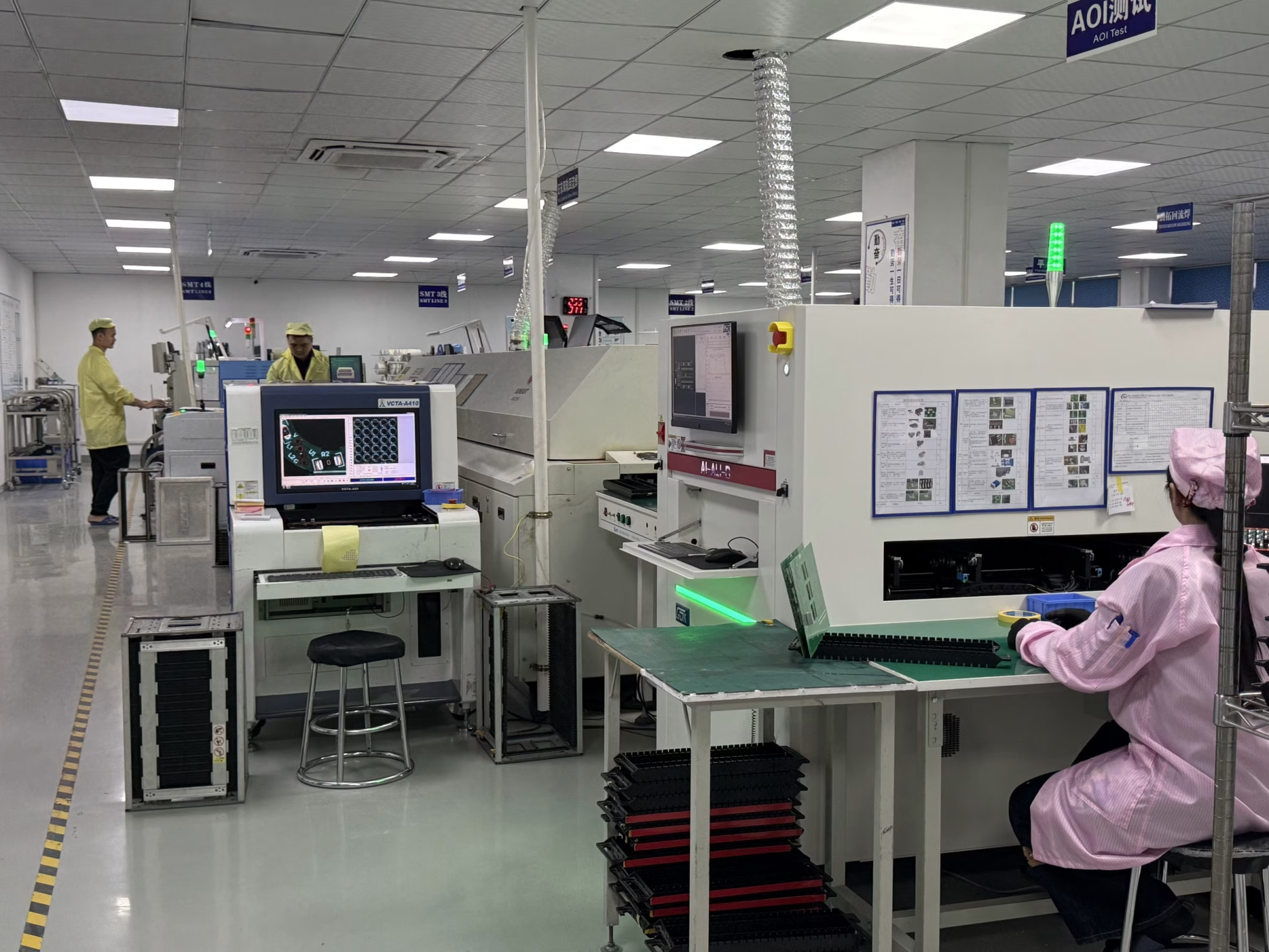
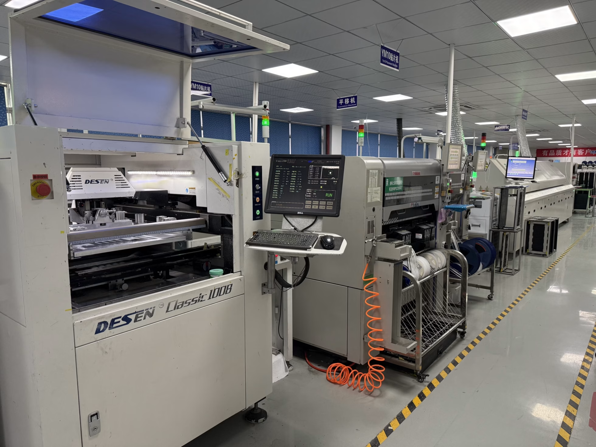
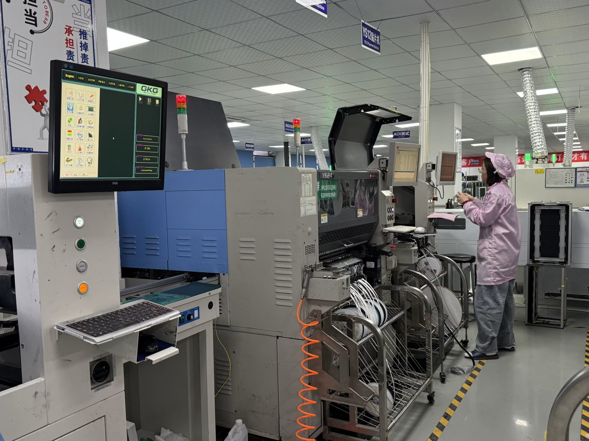
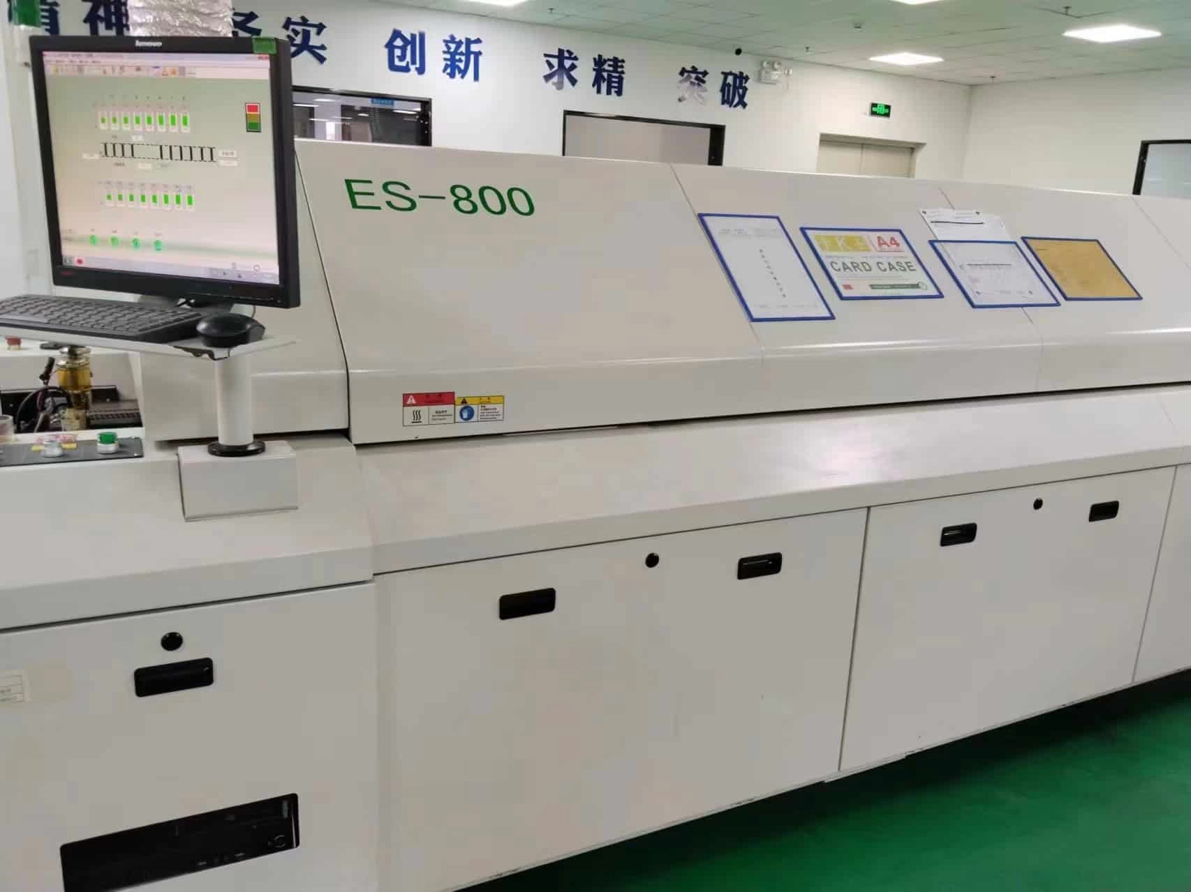
PCB Factory Gallery