
Controlled Impedance PCB Fabrication & Assembly
OrinewPCB manufactures controlled-impedance PCBs for high-speed digital, RF and mixed-signal designs, then supports one-stop component sourcing and assembly. Share your impedance targets, stackup and files so our engineers can review trace geometry, material, test method, price and lead time for your project.
ISO 9001/UL Certified
PCB Assembly Specialists
Fast, Project-Based Lead Times
Nine-Step Quality Workflow
Schedule Confirmed After Review
ISO 9001/UL Certified
PCB Assembly Specialists
Fast, Project-Based Lead Times
Nine-Step Quality Workflow
Schedule Confirmed After Review
What is Impedance Control in PCB?
Impedance is a measure of the total opposition that a circuit presents to alternating current (AC) when a voltage is applied. An impedance value is usually represented by the symbol Z and is measured in ohms (Ω). Moreover, impedance is an important concept in electrical engineering and electronics.
As electronic devices advance, they use more powerful components and drivers that communicate through high-power, high-frequency signals. Traditional copper signal trace designs are not capable of handling this performance. However, you can design a controlled impedance PCB to take care of this.
Controlled impedance helps reduce reflections when trace geometry, reference planes and dielectric properties are designed for the required signal interface. It does not simply mean making every trace wider or thicker. At OrinewPCB, our manufacturing process places a focus on controlled impedance designs to ensure optimal performance for high-speed applications. If you’re interested in our services, feel free to request a PCB assembly quote to learn more!
50 Ω
Standard impedance value used in many high-frequency applications, including radio frequency (RF) circuits and test equipment
75 Ω
Used in video and cable television applications
100 Ω
Often used in differential impedance signaling applications, such as Ethernet and USB
300 Ω
Used in some antenna systems and older television applications
How to Achieve Impedance Controlled PCBs
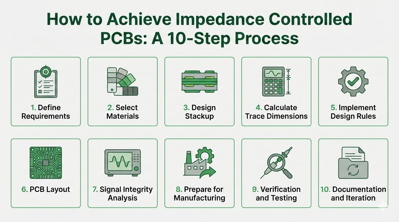
1. Define Controlled Impedance Requirements
First define the impedance target for each relevant net class and whether it is single-ended or differential. Values such as 50 Ω single-ended or 90/100 Ω differential are examples; use the requirement of your actual interface and component design. Then, you’re going to have to determine the frequency range of operation, as this affects the material selection and design rules.
2. Select Appropriate Materials
It’s important to choose the right PCB stackup. Select laminate properties according to your frequency, loss budget, stackup and cost requirements; FR-4 may fit some projects, while others need a lower-loss material.
Lower dielectric constant (Dk) materials typically offer improved performance, while lower dissipation factor (Df) reduces signal loss. Then, be sure to choose the correct copper weight, often between 0.5 to 2 oz per square foot
3. Design the PCB Stackup
Start by figuring out how many layers you’ll need; more layers provide you with better control, but they also increase the cost.
Arrange the signal and plane layers, typically as signal-ground-power-signal. Then, you’ll calculate the dielectric thickness using impedance calculators or specialized software. For more complex designs, you might want to use buried and blind vias.
4. Calculate Trace Dimensions
Use impedance calculation formulas or software to calculate trace dimensions. You’ll need to determine trace width and spacing and adjust these to calculate the impedance value. Also, keep in mind manufacturing tolerances. If you have differential pairs, you’ll have to calculate the individual trace width and the spacing between traces.
5. Implement Design Rules
Set up the trace width and spacing rules in your CAD software and define size, spacing, and type via routes. Then you need to establish clearance rules for between traces, pads, and planes. Create length-matching rules for differential pairs.
6. PCB Layout
Place components to minimize critical trace lengths. Route critical signals first with consistent width and smooth bends. Use reference planes for return paths and route differential pairs as parallel, equal-length traces with length matching. Finally, add guard traces and stitching vias to control crosstalk.
7. Signal Integrity Analysis
Start by performing a pre-layout simulation using tools like HyperLynx or HFSS. Then, conduct a post-layout simulation to verify impedance control and make sure to check for reflections, crosstalk, and EMI issues.
Analyze eye diagrams to ensure that signal quality meets specifications and iterate design if necessary by adjusting trace widths, spacings, or stackup.
8. Prepare for Manufacturing
Generate accurate Gerber files and include impedance requirements in fabrication notes. Specify impedance control requirements, including target impedances for different trace types and acceptable tolerance ranges.
Then, request impedance coupons and test structures for impedance verification. Finally, choose a PCB manufacturer experienced in characteristic impedance control, like OrinewPCB.
9. Verification and Testing
Agree on fabrication coupon and TDR requirements before production. If the application calls for higher-frequency S-parameter measurements, specify that separately for engineering review. Then, conduct functional testing to ensure the PCB meets performance requirements. Analyze test results and make adjustments if necessary.
10. Documentation and Iteration
Document all design decisions and test results
Create a report detailing impedance control achievements
Use insights gained to improve future designs
Consider creating design guidelines for your organization
PCB Assembly Services
Turnkey PCB Assembly
We coordinate fabrication, 100% brand-new original component sourcing, SMT/THT assembly and a project-specific quality plan for your assembled boards.
Prototype & Full Production Runs
Whether you need a few prototypes or large-volume batches, our flexible assembly services adapt to your project’s scope and timeline.
RoHS & Lead-Free Compliance
Stay environmentally responsible with our compliant assembly processes, offering RoHS and lead-free options for safe, reliable builds.
Single-Sided, Double-Sided, or Mixed
No matter the complexity, we can assemble boards of all configurations—single-layer, multi-layer, or a mix—to match your exact specifications.
Small Quantities & High-Volume Capabilities
From one-off prototypes to bulk orders, we accommodate projects of all sizes without compromising on quality or turnaround time.
Built for High-Mix, Low-Volume PCBA
Build several board variants or a small production run through one team, with transparent review of materials, quality checks, pricing and schedule.
Technical Capabilities
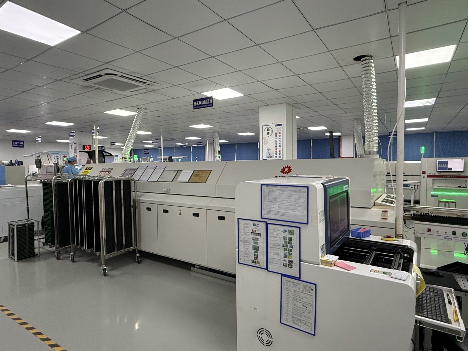
Capabilities & Services
One-stop PCBA Services (PCB Manufacturing + Components Sourcing + Assembly)
SMT Assembly + THT Assembly, Single/double-sided Assembly Mixed PCB Assembly
BGA Rework
60,000 Chips/Hour
Down to 01005/0210 Size
Accuracy<±40μm
Min. QFN Pin Width/Space: 0.15mm/0.25mm
Min. BGA Diameter/Space: 0.2mm/0.35mm
Rigid, Flex, HDI, & High-speed Power Boards
Up to 64 Layers
60GHz High Frequencies
Min. Trace Width/Spacing: 1.8mil/1.8mil
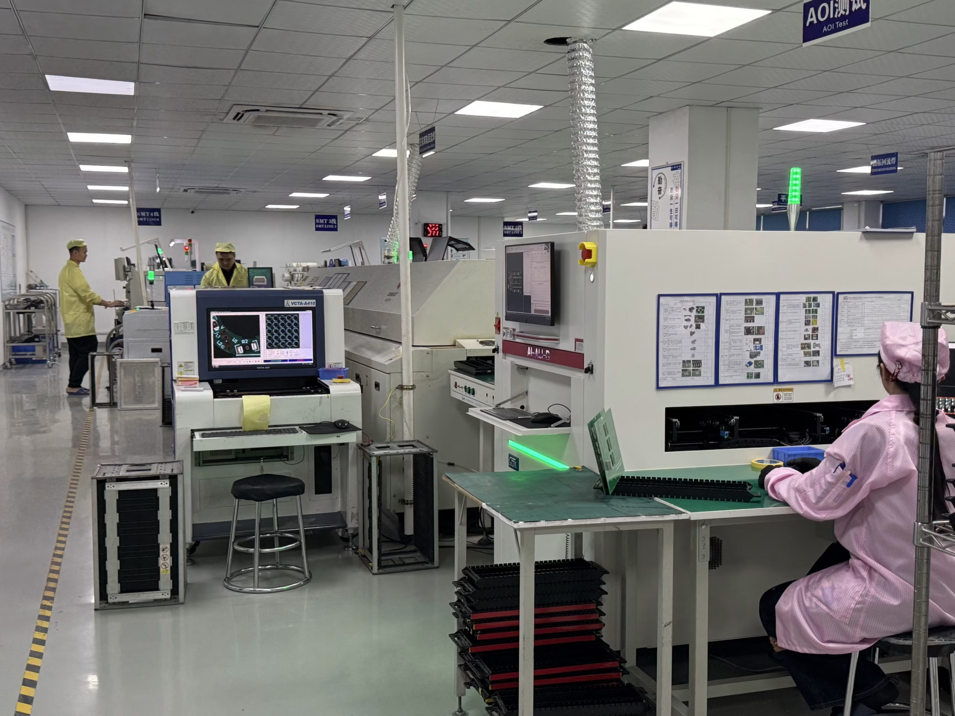
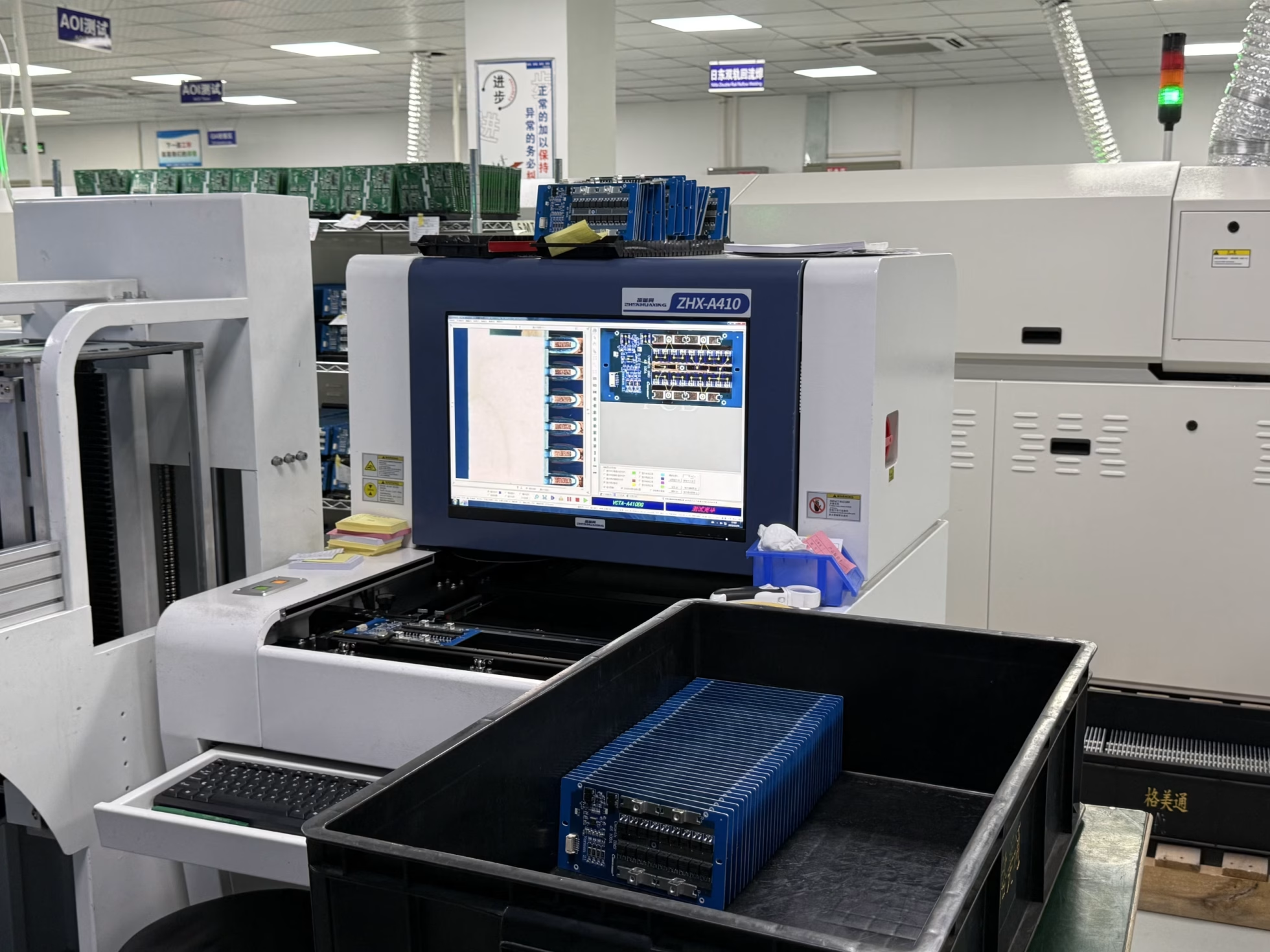
AOI, X-ray, ICT & FCT Testing
Controlled Impedance
ISO 9001, ISO 13485, ISO 14001, IATF 16949, IPC-A-610, UL Certified
Automotive, Medical, & Military-grade PCBA Manufacturing
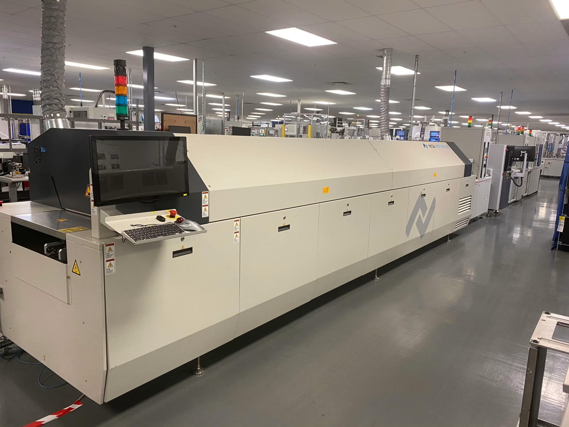
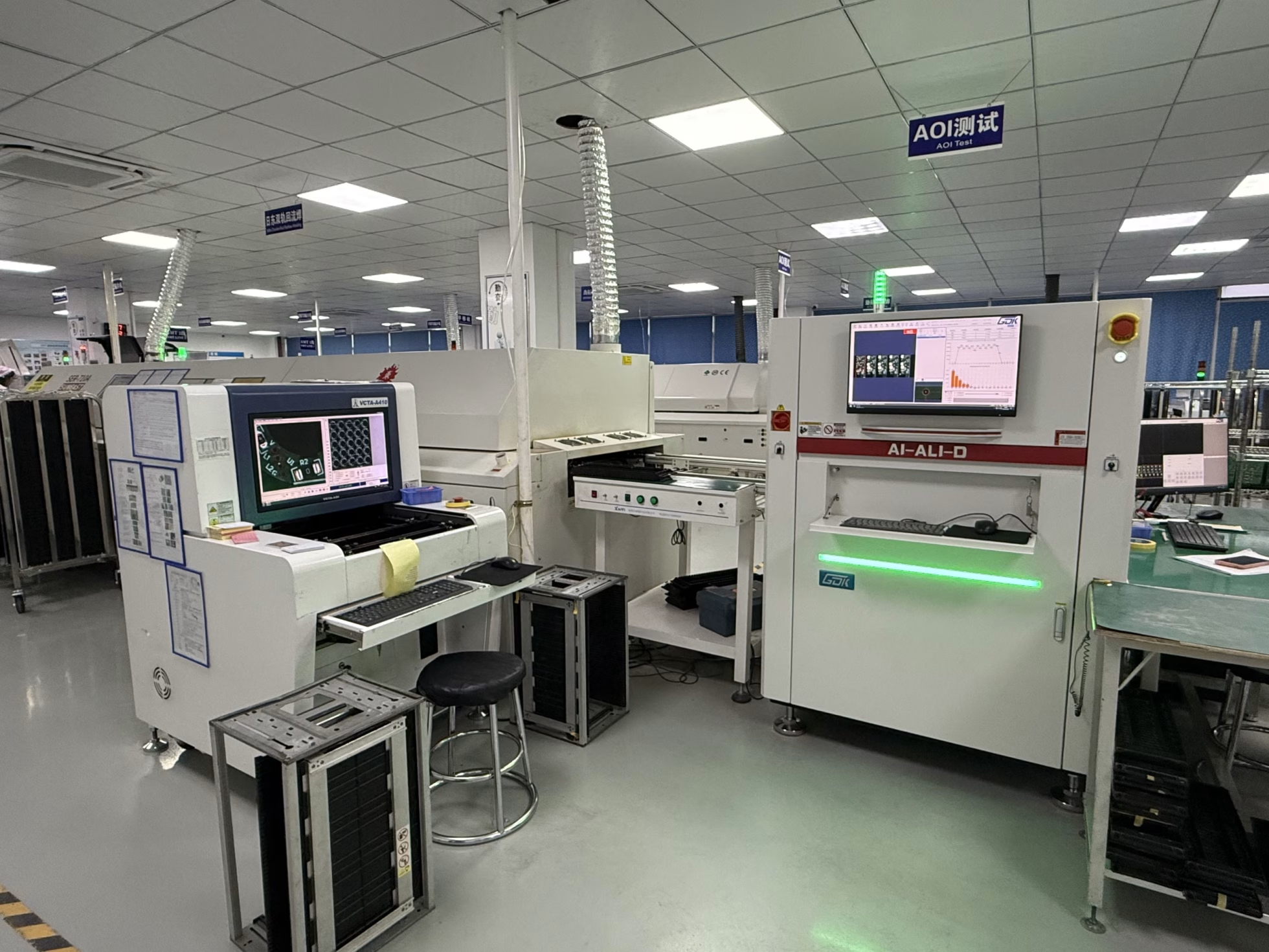
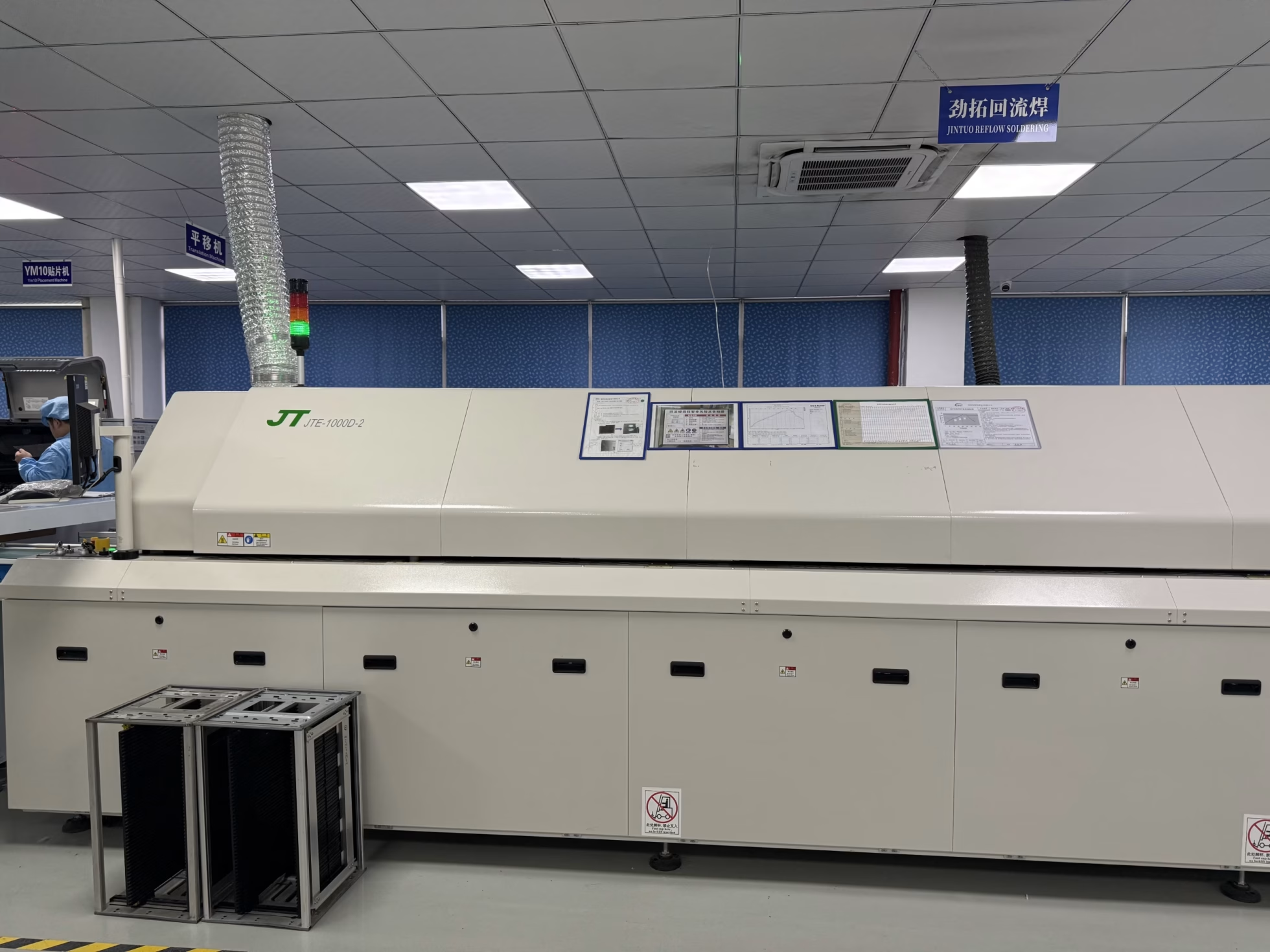
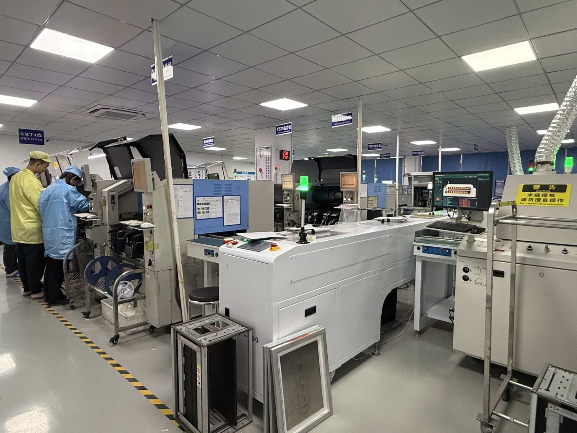
PCB Factory Gallery
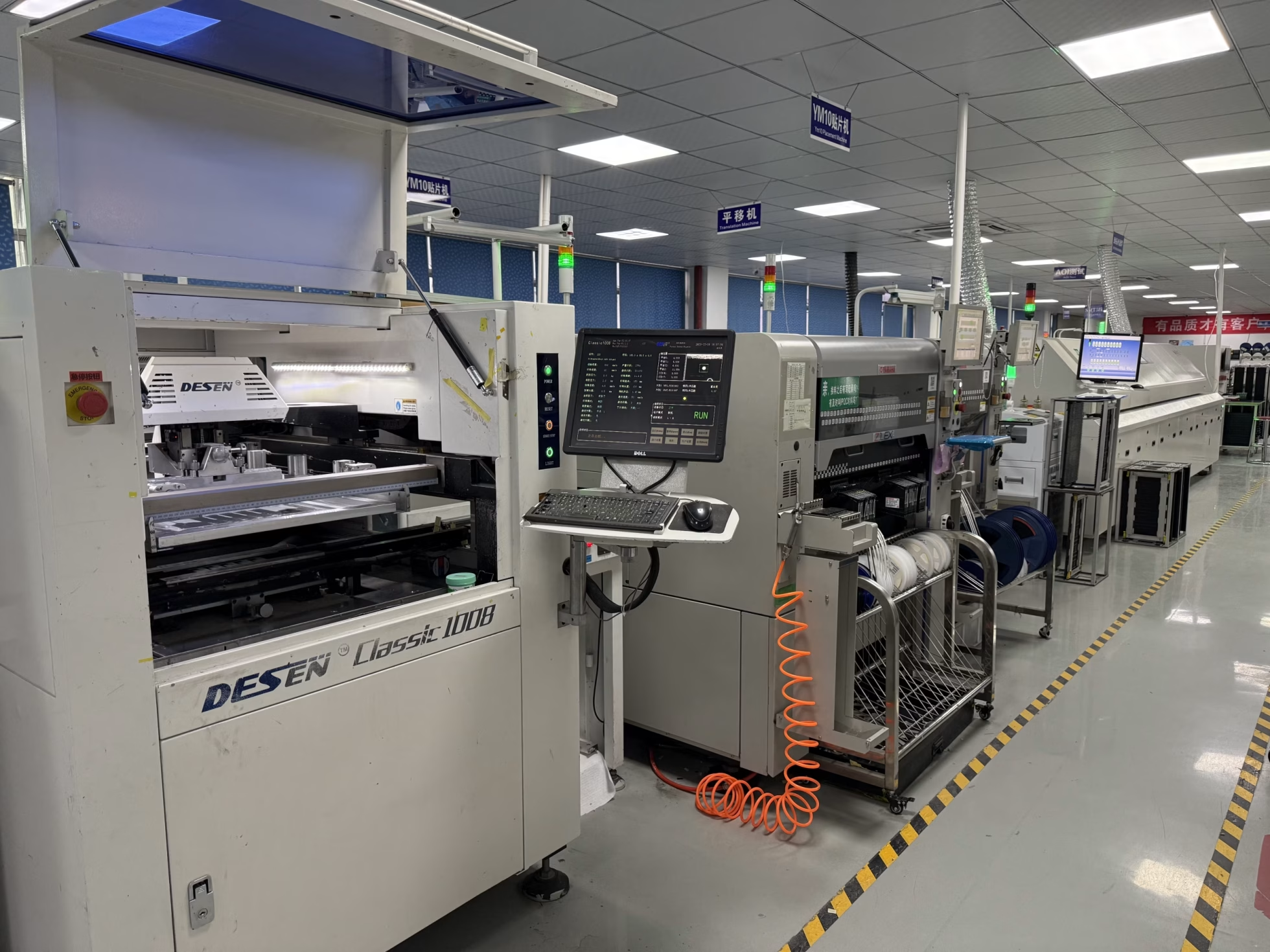
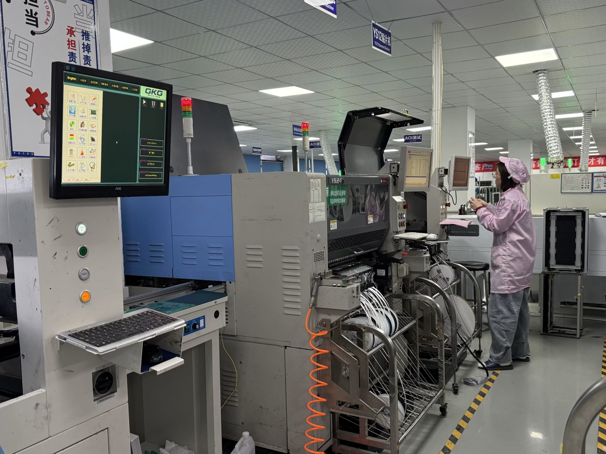
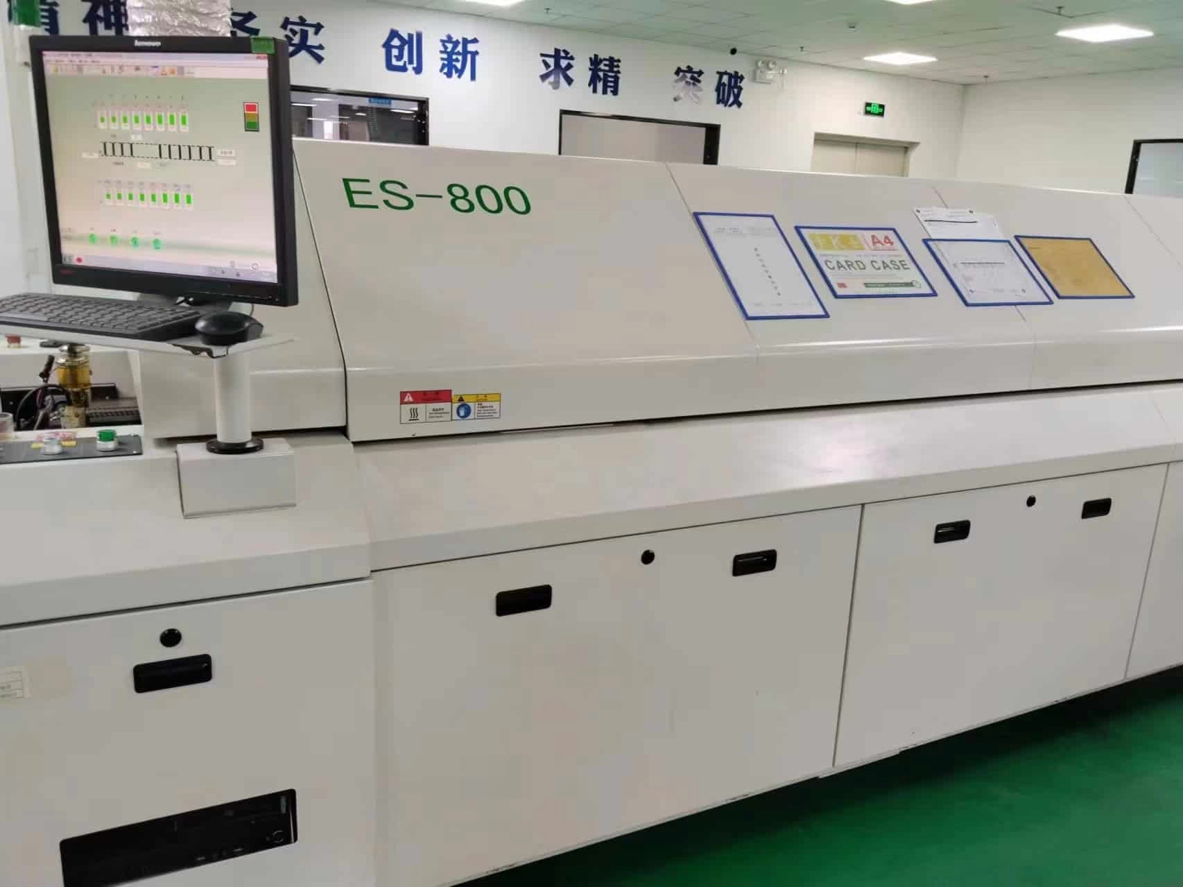

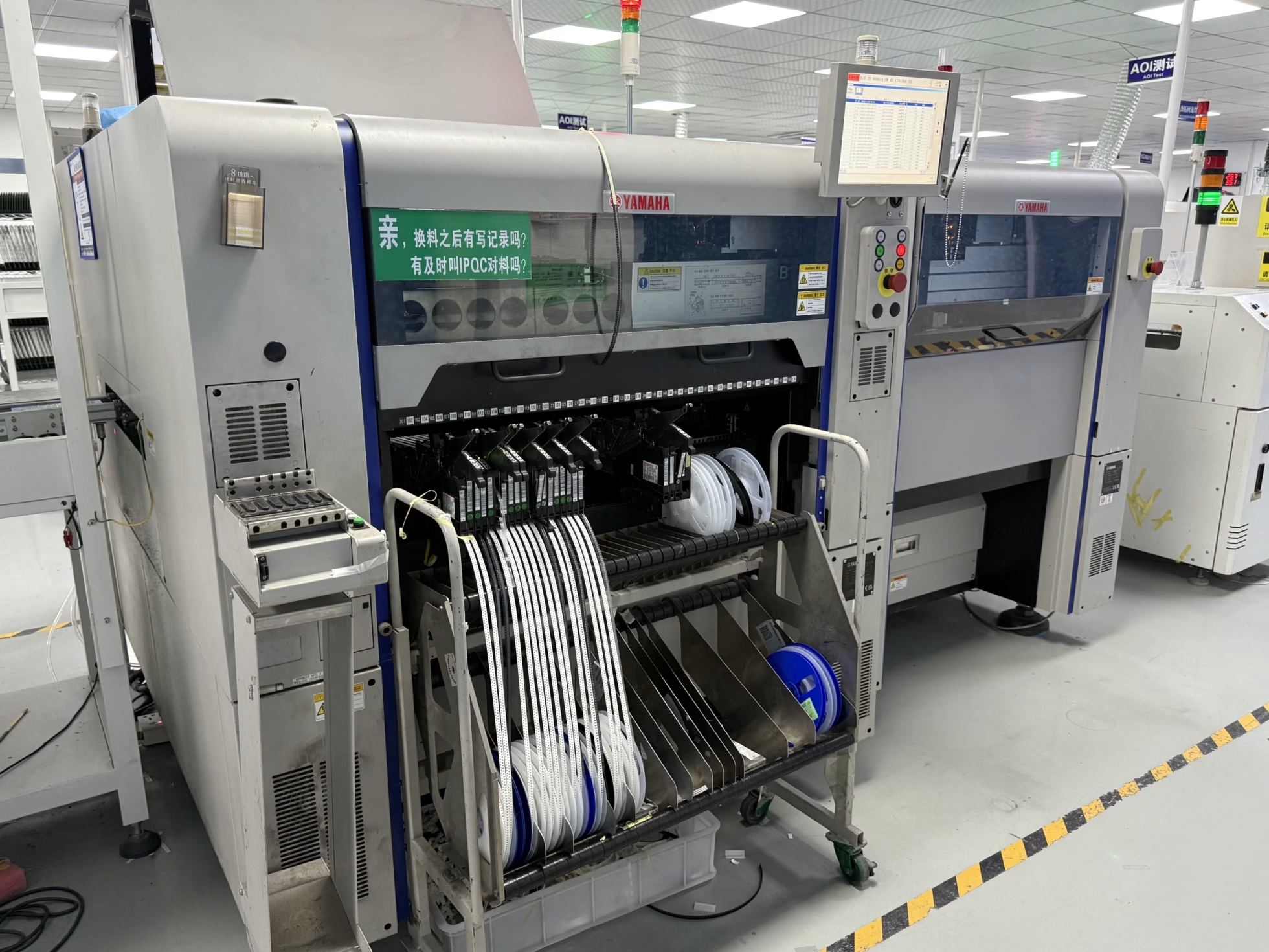
CONTROLLED IMPEDANCE + ONE-STOP PCBA
From impedance-controlled PCB fabrication to assembled boards
OrinewPCB reviews the target impedance and stackup alongside component availability, assembly and test needs. This coordinated approach is especially useful for high-mix, low-volume PCB assembly: one team can quote the bare board, 100% brand-new original components, SMT/THT assembly and project-specific quality checks together.
Engineer the board first
Share the target for each single-ended or differential net, its signal layer, reference plane, stackup and permitted tolerance. We review manufacturability and agree on the verification method before production.
Source and assemble in one flow
Our manufacturer and distributor relationships help us seek competitive component pricing and availability. Board fabrication, original-part sourcing and assembly can then follow a coordinated schedule.
Quality and delivery you can plan
Our nine-step quality workflow supports the build; the exact inspection and electrical or functional tests are agreed for your design. We confirm the fastest practical lead time after reviewing files and material supply.
Request a controlled-impedance PCBA quote
Send Gerber/drill files, stackup, impedance table, BOM, pick-and-place data, quantities and target date. We will review cost, test approach and delivery together.
ENGINEERING & RFQ GUIDE
What to specify for controlled impedance
Controlled impedance is a fabrication requirement for transmission-line traces. It is separate from assembled-board functional testing; both can be included in one PCBA project when specified.
| RFQ item | What to provide | Why it matters |
|---|---|---|
| Impedance targets | Single-ended or differential value for each net class, signal layer and allowable tolerance | Defines the fabrication and acceptance targets without assuming one value fits every interface. |
| Stackup and material | Layer order, copper thickness, dielectric thickness, preferred laminate and frequency or rise-time context | Trace geometry, reference plane and dielectric properties affect the final impedance and loss. |
| Verification | Whether test coupons and TDR data are required; any reporting or high-frequency measurements | Sets an agreed method to check fabricated boards. Assembly tests answer different questions. |
| Assembly package | Gerber/drill or CAD files, BOM with manufacturer part numbers, pick-and-place, drawings, quantity and target date | Lets OrinewPCB quote board fabrication, authentic parts, assembly and the fastest practical schedule together. |
Learn more about our PCB manufacturing capabilities and turnkey PCB assembly. Final impedance tolerance, materials, test scope, pricing and lead time are confirmed after engineering review.