
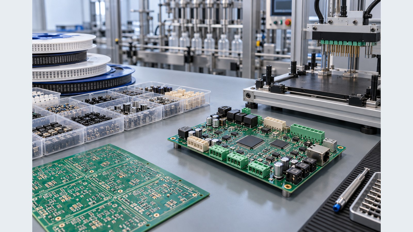

Fabricated boards for design validation and controlled first builds
Prototype PCB manufacturing produces a small quantity of bare circuit boards so an engineering team can validate the released layout, stackup, holes, finish and manufacturability before a larger commitment. A PCB prototype is most useful when it has a defined learning goal: mechanical fit, power integrity, signal behavior, assembly process, programming or functional test. Ordering boards without a controlled revision and acceptance plan can create activity without producing reliable engineering evidence.
For projects that need more than bare boards, OrinewPCB can coordinate prototype PCB fabrication with 100% new and original component sourcing, SMT and through-hole assembly, inspection and project-specific testing. This one-stop route reduces handoffs between the board shop, component supplier and assembler, while keeping substitutions, rework and test findings connected to the correct revision.
When should you choose Prototype PCB?
The correct route is the simplest construction that satisfies the released electrical, mechanical, thermal, compliance and assembly requirements. Use the comparison below to define why this board type is necessary before specifying details.
| Route | Use it when | Release decision |
|---|---|---|
| Bare PCB prototype | Validate board construction, fit or routing before purchasing components | Fabrication data, quantity, finish and dimensional requirements |
| Assembled engineering prototype | Validate placement, soldering, power-up or firmware | Gerber/ODB++, BOM, CPL, drawing and test definition |
| Small pilot batch | Confirm repeatability after prototype corrections are released | Controlled ECO closure, approved alternates and production test limits |
| Multiple variants | Compare population or design options | Distinct revision and variant identifiers with quantity per option |
Prototype PCB design and DFM controls
The most useful DFM review checks the features that control fabrication and assembly risk, rather than comparing the design with a generic capability list.
Define the experiment
State what the build must prove and what evidence will close the decision. Mechanical fit and functional behavior need different quantities and tests.
Freeze one fabrication revision
Do not mix Gerber, drill, drawing or stackup files from different export dates. Mark preliminary files clearly.
Plan debug access
Test points, programming headers, connectors, fixtures and safe power-up limits should be available before assembly.
Capture every correction
A wire modification or alternate part is evidence, not a production baseline. Update the released files before repeating the build.
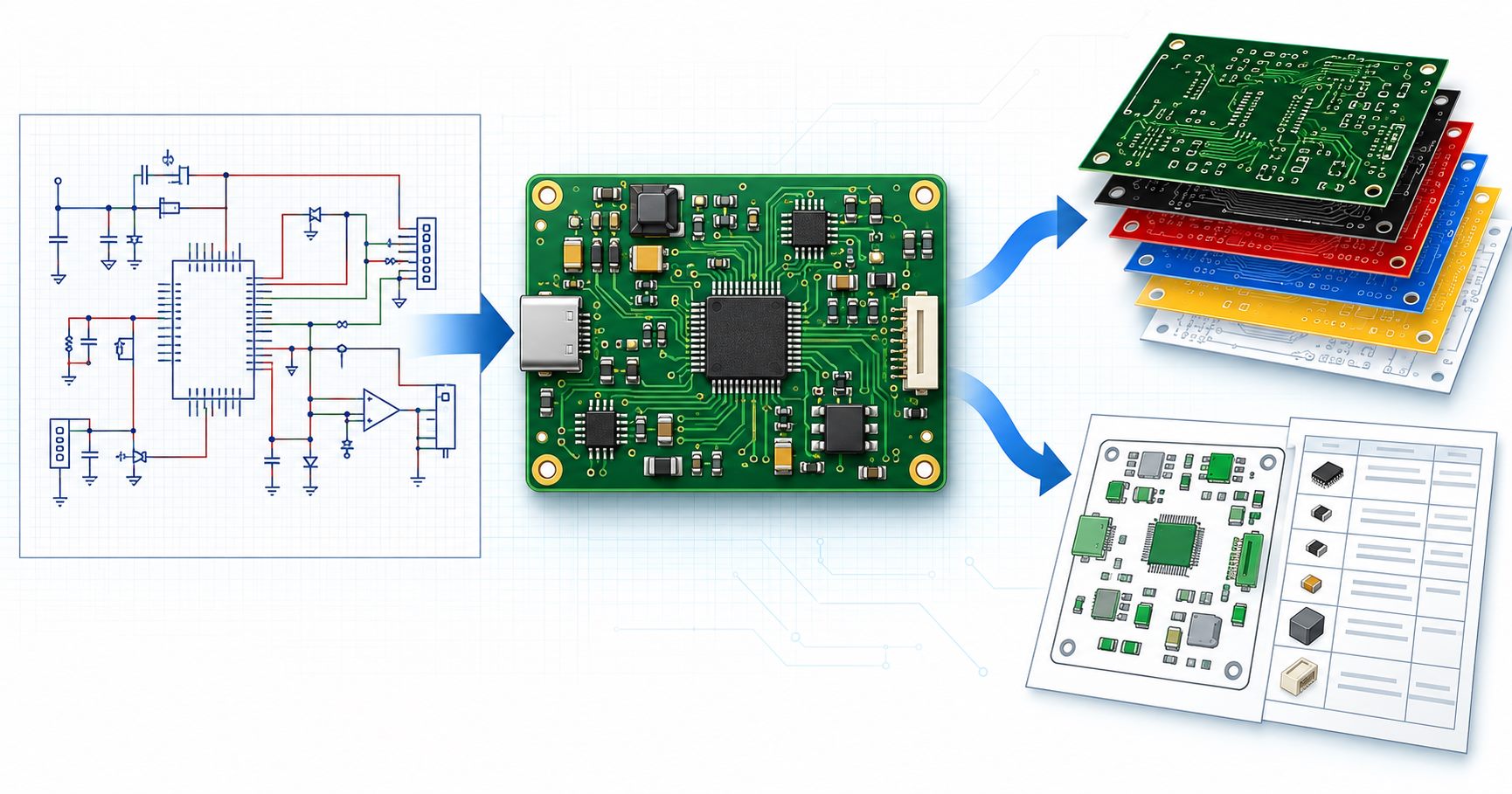
How the manufacturing route is reviewed
A reliable build keeps the requirement, material, fabrication data and acceptance evidence connected through the release process. The exact operations vary with construction, but the following gates should be explicit.
- Scope the learning goal: Decide which design, fabrication, sourcing or test question the prototype must answer.
- Review the data package: Align PCB files, BOM, placement, drawing and test revision.
- Fabricate the boards: Build the released construction and complete the agreed bare-board checks.
- Source and kit components: Confirm exact MPNs, approved channels and substitutions for assembled prototypes.
- Assemble and inspect: Use the appropriate SMT, through-hole and first-article route.
- Close the loop: Record findings and release corrected data before the next lot.
Files to send for an engineering review
Every file should identify the same board revision. A complete package shortens clarification time and makes price, material and delivery assumptions visible before production.
| Input | Required detail | Decision supported |
|---|---|---|
| Fabrication data | Gerber, ODB++ or IPC-2581 plus NC drill and board outline | Layer interpretation, holes, profile and DFM review |
| Stackup and materials | Layer order, finished thickness, copper, material and approved-equivalent rules | Construction and material proposal |
| Special requirements | Impedance, mechanical, compliance, finish, marking or documentation needs | Process selection and quotation scope |
| Assembly package | BOM, CPL, assembly drawing, variants and substitution rules when PCBA is required | Original-part sourcing and assembly planning |
| Test and delivery | Acceptance method, required evidence, quantity and target delivery | Inspection, test and schedule basis |
When the release package is ready, share the fabrication files and assembly inputs for a combined engineering review. OrinewPCB can then identify open DFM, material, sourcing and test questions before confirming the quotation scope.
Prototype PCB in one-stop PCB assembly
A bare PCB prototype answers only board-level questions. If the actual risk is package fit, polarity, soldering, programming or functional behavior, the build should include assembly evidence. The dedicated prototype PCB assembly service explains the first-article, sourcing and test inputs needed for an assembled engineering build.
Use the four-layer PCB guide when the prototype needs defined reference planes, and review the PCB manufacturing scope before choosing a special construction. For a combined board and material order, see turnkey PCB assembly.
Quality, cost and lead-time factors
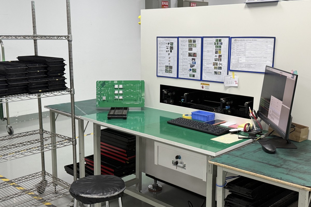
OrinewPCB uses a nine-step quality and test control framework that links release review, materials, fabrication, assembly and final verification. The actual inspection and test methods are selected for the board and customer-defined acceptance scope; not every board needs every method.
Prototype cost is dominated by one-time engineering, tooling, panel use, uncommon materials, component packaging and test preparation. A slightly larger first lot can be sensible when it covers debug losses and retained samples, but quantity should follow the learning plan rather than an arbitrary unit-price target.
- Resolve missing or conflicting data before material is committed.
- Keep approved substitutions and evidence requirements in the released order.
- Confirm panel, tooling and assembly constraints together when PCBA is included.
- Plan delivery as early as practical after material, process and test inputs are reviewed.
Prototype PCB FAQ
What is prototype PCB manufacturing?
It is a small-quantity fabrication build used to validate a released PCB design and its manufacturing assumptions before a larger order.
How many prototype PCBs should I order?
Order enough to cover the intended tests, debug losses, customer evaluation and retained samples. The practical quantity depends on the learning goal and panel use.
Can prototype PCBs include assembly?
Yes. One-stop prototype PCBA can include board fabrication, original component sourcing, assembly, inspection and an agreed test plan.
What should happen after prototype rework?
Update the PCB data, BOM, placement file, drawing and test instructions so the next build uses a controlled baseline rather than remembered corrections.
Plan the next build from one controlled data set
The board construction, component BOM, assembly revision and acceptance plan should describe the same product. This reduces supplier handoffs and makes engineering decisions easier to trace across prototypes, small-to-medium batches and high-mix production.
If the project is ready to move forward, provide the released PCB data, BOM, quantities and test requirements for the next-build review. The returned scope can address fabrication, 100% new and original component sourcing, assembly, testing and the earliest practical delivery plan together.