
Rigid-Flex PCB Assembly

OrinewPCB · One-stop specialized PCBA
Rigid-flex PCB assembly with the flex-to-rigid transition under control
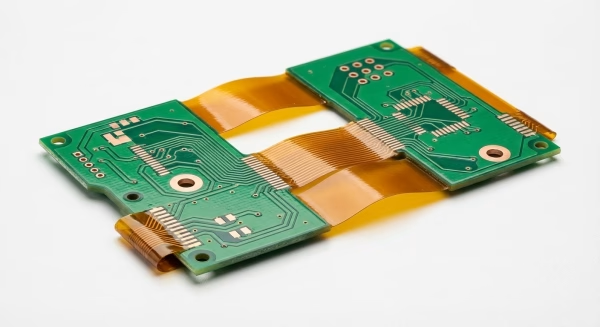
Rigid-flex PCB assembly combines components on rigid sections with integral flexible interconnects, so fabrication, carrier design, handling, soldering and final-form testing must be reviewed together. OrinewPCB coordinates board fabrication, 100% new original components, assembly and agreed verification for prototypes and high-mix, low- to medium-volume programs.
The highest-risk area is often not the visible component field but the relationship between rigid islands, flex layers, coverlay, stiffeners and transition zones. A build package should identify the finished mechanical state, fold or bend constraints, connector forces and test access before price and delivery are confirmed.
High-mix, practical quantities
OrinewPCB coordinates prototypes and low- to medium-volume builds, including several board variants, without losing revision and material ownership.
100% new, original parts
For components sourced by OrinewPCB, the requirement is 100% new and original. Manufacturer and distributor cooperation supports price, availability and lead-time review.
Quality and delivery together
The nine-step workflow remains in the plan while engineering and purchasing work toward the earliest practical delivery after files, materials and tests are reviewable.
Design-to-process decisions
Review the complete rigid-flex construction before assembly
Rigid-flex design data must describe a continuous structure. Separating the rigid board drawing from the flex behavior can hide conflicts that only appear during tooling, folding or final installation.
| Decision area | What to provide | What OrinewPCB reviews |
|---|---|---|
| Stack-up | Rigid and flex layer sequence, materials, copper, coverlay and adhesive | Fabrication route and thermal compatibility |
| Transition zones | Rigid-to-flex boundaries, fillets, coverlay ends, keep-outs and vias | Stress concentration and handling risk |
| Mechanical form | Bend radius, fold sequence, installation envelope and connector loads | Carrier, assembly sequence and final inspection state |
| Panel support | Array, rails, tooling holes and permitted support surfaces | Stable printing, placement, reflow and depaneling |
| Acceptance | Critical dimensions, test points, firmware, fixtures and records | Defined evidence before shipment |
If the product uses separate flex cables connected to rigid boards, it is not necessarily a rigid-flex PCB. Identify the actual construction so fabrication data, sourcing and assembly responsibility are quoted correctly.
Share the released data set for a combined engineering and BOM review. The quotation can then state the fabrication, sourcing, assembly, inspection and test assumptions together.
Nine controlled quality gates
A one-stop workflow for the complete assembly
A specialized board still needs the same configuration discipline as any repeatable PCBA. The method below connects procurement, process setup and acceptance evidence; it is not a claim that every product receives identical equipment or every optional test.
- Data and revision review: Reconcile fabrication files, BOM, placement data, drawings, quantities and product variants before material release.
- Source and material identity: Confirm PCB material requirements and exact manufacturer part numbers; any alternate remains subject to the agreed approval rule.
- Incoming inspection: Check received bare boards and components against the released order and the condition required for production.
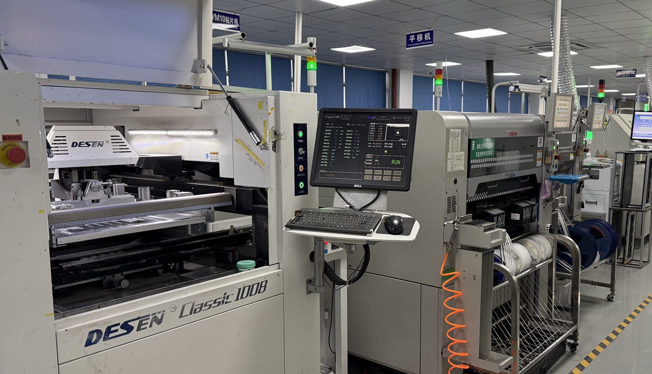
- Process setup and solder paste: Prepare stencil, tooling, support, feeders and solder-paste controls for the actual board construction.
- First-article verification: Verify polarity, orientation, fitted references and critical assembly attributes before the lot continues.
- AOI or visual inspection: Inspect visible soldering and placement attributes using the method appropriate to the board and package mix.
- X-ray where appropriate: Use X-ray when selected hidden joints or package structures require evidence that visible inspection cannot provide.
- Electrical or functional test: Apply the agreed test method, fixtures, firmware, limits and failure disposition for the product.
- Final quality and release: Reconcile quantity, records, approved deviations, packing and shipment release against the order.
Inspection scope is product-specific. AOI, X-ray, electrical testing and functional testing answer different questions. The applicable coverage depends on component packages, visibility, test access, fixtures, software and customer acceptance criteria.
Board-specific process control
Protect transition zones while supporting rigid sections
Tooling should support the rigid component areas without forcing the flex into a harmful radius or clamping across transition zones. The panel and depanel method should also avoid tearing coverlay or transmitting shock into the flexible layers.
Component placement, connector insertion and rework can apply local force. The work instruction should define how the assembly is held, which sections may be contacted and when the circuit is moved from flat production tooling to its intended installed shape.
Final inspection and testing should state the mechanical condition. A flat electrical check may not represent connector alignment or behavior in the installed fold, while repeated dynamic flexing should never be assumed unless the design and qualification require it.
Original components · Coordinated supply
Component sourcing, cost and delivery are connected
Material price is only useful when the exact manufacturer part number, packaging, quantity and delivery window are correct for the released BOM. OrinewPCB checks manufacturer and distributor channels for genuine supply, available price breaks and practical lead time. We do not replace an approved component without the defined customer decision.
| Project input | How it supports cost | How it supports delivery |
|---|---|---|
| Exact manufacturer part numbers | Prevents quotes based on a different grade, package or lifecycle status. | Lets purchasing check real stock and authorized supply paths immediately. |
| Approved alternatives and authority | Creates a controlled comparison instead of an unreviewed substitution. | Reduces waiting when the preferred part is constrained. |
| Quantity by board variant | Allocates common material and setup cost to the correct models. | Supports a coordinated high-mix build sequence and material plan. |
| Firmware and test readiness | Shows programming, fixture and labor scope before the quote is confirmed. | Prevents assembled boards from waiting for an undefined acceptance method. |
For a wider responsibility matrix, review turnkey PCB assembly. For several models in practical quantities, the low-volume, high-mix PCB assembly page explains why variant control matters.
Build-ready information
What to send for an accurate PCBA review
- Gerber or ODB++, drill files, stack-up, board drawing and material requirements.
- BOM with exact MPNs, references, quantities, DNP lines and approved-alternate rules.
- Centroid or pick-and-place data, assembly drawings, polarity and mechanical notes.
- Quantity and revision for every board model or variant.
- Programming files, test instructions, fixtures, pass limits, records and target date.
Files should identify the same release. Mark preliminary data clearly and list unresolved decisions; a fast response is more reliable when engineering does not need to infer which version governs the build.
Related service detail is available in the flexible PCB assembly service and one-stop PCB assembly pages.
From first build to repeat order
Keep the high-mix program traceable after the first shipment
The final production record should identify the actual PCB revision, installed manufacturer part numbers, approved alternates, programming version, inspection findings, rework and test limits. A repeat order should begin from that evidence and a newly reviewed release, not from an assumption that every file and component is unchanged.
For several product variants, use a configuration matrix that separates shared material from model-specific parts, DNP positions, firmware and test instructions. Common purchasing can support competitive component cost and supply planning, while separate traveler or lot records preserve the identity of each finished model. When one variant changes, state whether existing boards, components, stencil, fixtures or programs remain valid for the others.
Nonconformities also need a documented decision. Define who can approve a controlled deviation, alternate or rework, what evidence is required after correction and whether the disposition applies to one board, one lot or future releases. This prevents a fast answer during an urgent build from becoming an unintended permanent change.
Forecast information can help purchasing review allocation and common materials, but forecast demand should remain distinct from an authorized order. State likely quantities and timing separately from firm release quantities. For a new design, prototype PCB assembly can establish the build and test baseline before recurring low- or medium-volume production.
Frequently asked questions
Rigid-Flex PCB Assembly Services FAQ
These answers describe the manufacturing review boundary. The approved quotation, released product data and agreed acceptance plan remain the controlling documents for each order and variant.
What is rigid-flex PCB assembly?
It is component assembly on a PCB construction that integrates rigid component areas and flexible interconnect layers into one board.
What files are needed for a rigid-flex quote?
Provide the complete stack-up, fabrication and drill data, mechanical and bend requirements, BOM, placement data, drawings, quantities and test definition.
How are flex-to-rigid transitions protected?
The design should define transition geometry and keep-outs. Tooling, support, handling, rework and depanel instructions are then planned to avoid uncontrolled stress.
Can OrinewPCB source the components?
Yes. For material sourced by OrinewPCB, the requirement is 100% new and original components, with substitutions controlled by the agreed approval rule.
How is delivery confirmed?
We review the rigid-flex construction, material availability, component stock, quantity, tooling and test scope before confirming the earliest practical schedule.
Share the complete rigid-flex stack-up, mechanical form, BOM, placement package, quantities and test requirements. The review will separate confirmed capability from open engineering decisions.
Send the BOM, board files, quantities and target date for a project-specific quote.
US keyword data used for this update: rigid flex pcb assembly (30 monthly searches; keyword difficulty 0).