OrinewPCB · Surface mount technology
SMT PCB Assembly Services
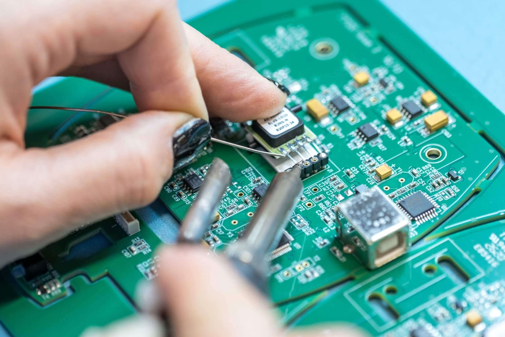
Surface mount technology (SMT) places and solders components directly onto PCB pads. OrinewPCB combines SMT assembly with PCB fabrication, 100% new original component sourcing, inspection and testing for prototypes and high-mix, low-volume builds.
Send one board design or several product variants. Our team reviews the files, BOM, test requirements and target date before confirming the complete PCBA quotation and fastest practical schedule.
- High-mix, low-volume focus
- 100% new original parts
- Nine-step quality workflow
One team for the whole PCBA
Coordinate PCB fabrication, parts, SMT/THT assembly and agreed testing through one point of contact.
Original parts, competitive sourcing
Deep cooperation with manufacturers and distributors supports genuine components, material pricing and availability.
Quality and delivery reviewed together
The build plan accounts for our nine-step quality workflow, component availability and target delivery date.
Assembly configuration
Choose the right surface mount assembly configuration
SMT can populate one or both sides of a board and can be combined with through-hole components. The practical decision is the component population, soldering sequence and inspection access—not the type label alone.
| Configuration | Component arrangement | What to confirm before production |
|---|---|---|
| Pure SMT — Type I | Surface-mount devices on one or both PCB sides, without through-hole parts. | Side-specific placement files, polarity, stencil design and any second-side reflow constraints. |
| Hybrid SMT and THT — Type II | Surface-mount devices and through-hole parts such as connectors or DIP packages. | SMT/reflow and THT soldering sequence, heat exposure and access for inspection and fixtures. |
| THT-dominant with passive SMT — Type III | Mainly through-hole parts with passive surface-mount devices on the other side. | Board-side population, component retention and the appropriate soldering method for the actual design. |
Type I/II/III terminology can vary by supplier. Use the BOM and assembly drawing to define the actual build. For a mixed design, review the through-hole assembly requirements alongside the SMT data.
From small batches to multiple variants
SMT assembly that fits a complete, high-mix PCBA order
A small batch still needs a controlled BOM, clear revisions and a defined test plan. OrinewPCB focuses on keeping these inputs coordinated when a project includes several board types or repeated design changes.
Prototype and small-batch builds
Provide quantities and revision identifiers for each board. We review setup, component supply and inspection needs before agreeing on the build scope.
Multiple designs and BOM variants
Identify shared components, do-not-populate positions and approved substitutions. Each variant needs the correct BOM, placement data and assembly instructions.
Turnkey fabrication and sourcing
Our one-stop PCB assembly service connects PCB fabrication, original electronic components, assembly and testing in one project.
The SMT manufacturing process
Five core stages from solder paste to a tested assembly
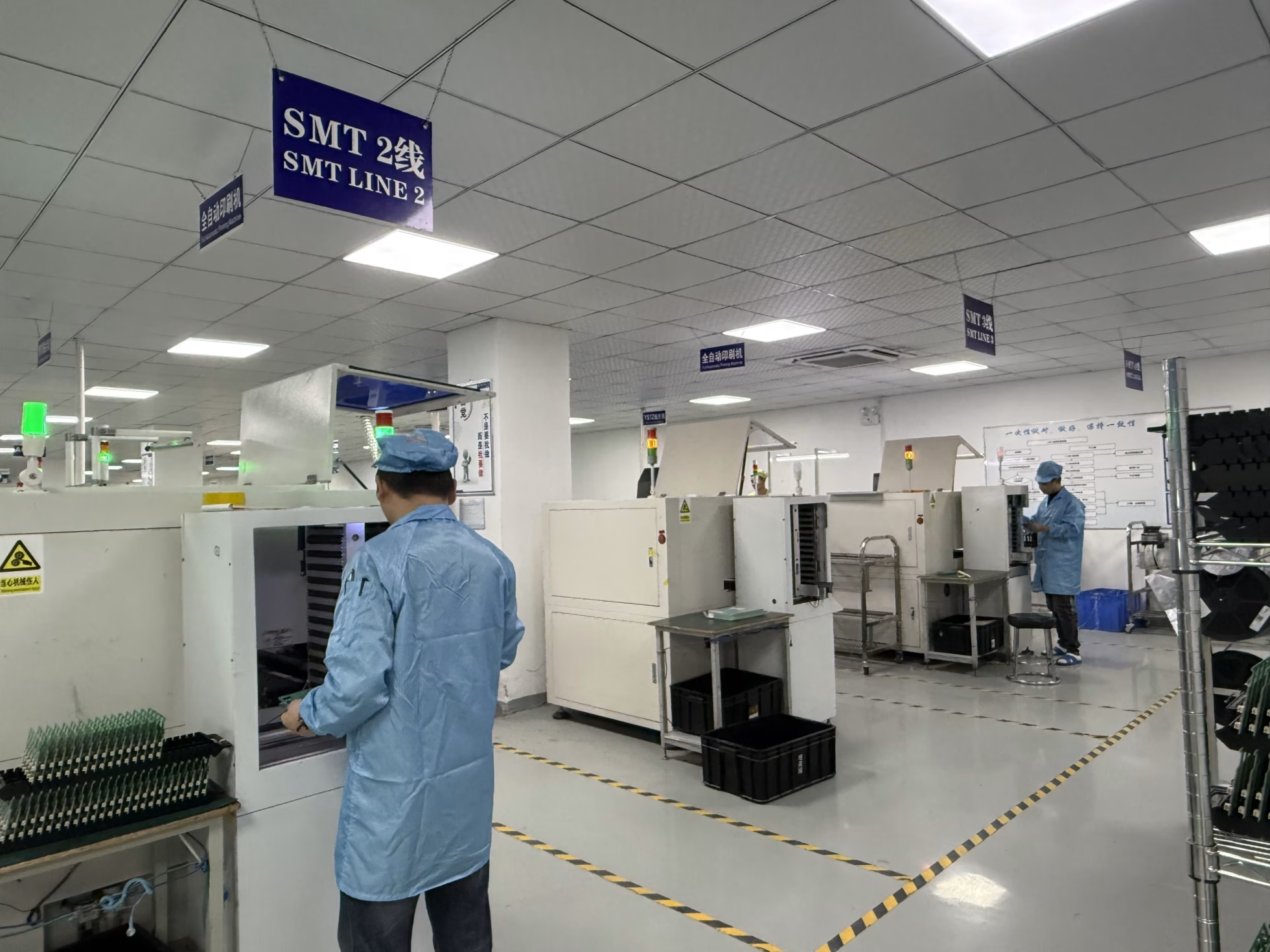
A typical SMT build moves through paste printing, component placement, reflow, inspection and testing. The exact work instructions and checkpoints depend on the board, component packages and agreed acceptance criteria.
-
Solder paste printing
A stencil transfers solder paste to the PCB pads. Apertures, alignment and paste condition are reviewed for the component land patterns; paste inspection can be included in the process plan where required.
-
Component placement
Pick-and-place equipment uses the placement data and BOM to position surface-mount parts. Correct manufacturer part numbers, orientation, polarity and board-side data are essential inputs. The automated PCB assembly process also depends on controlled programs, material setup and first-article verification.
-
Reflow soldering
The assembly passes through a controlled heating profile to form the solder joints. The profile must account for the solder paste, component guidance and the actual PCB; a single temperature or timing recipe does not fit every build.
-
Inspection
Visual or automated optical inspection checks accessible features. X-ray inspection can be specified for hidden joints where appropriate. Any rework requires a defined reinspection and acceptance process.
-
Testing
The agreed electrical and functional tests check different aspects of the product. Test-point access, firmware, fixtures and the pass/fail limits should be defined with the assembly package.
Original materials · Planned test coverage
A nine-step quality workflow, with tests matched to your board
OrinewPCB uses 100% brand-new original components and a nine-step quality and testing workflow. We confirm the inspections and tests applicable to your project before production; the named methods below serve different purposes.
Authentic component sourcing
We work with manufacturers and distributors to support original parts, competitive BOM pricing and practical material lead times. Define approved part numbers and alternatives in your BOM.
Revision and process control
Use a consistent revision across Gerbers, BOMs, placement files and drawings. Highlight differences between variants so materials and work instructions can be reviewed together.
Acceptance criteria first
Tell us which functions, programming, test access and records your project needs. This makes the quality plan and quotation scope clearer before the line is set up.
| Method | Primary purpose | Planning requirement |
|---|---|---|
| Visual inspection / AOI | Assess accessible placement and soldering features. | Package visibility and inspection criteria; hidden joints require another method. |
| X-ray inspection | Assess selected hidden solder-joint features where appropriate. | Relevant packages, coverage and acceptance limits agreed for the board. |
| ICT / electrical probing | Check specified component or interconnection characteristics. | Test access, coverage, programs and any fixture requirements. |
| Functional testing | Check powered behavior against the product’s defined functions. | Firmware, power/interface conditions and clear pass/fail limits. |
ICT and functional testing are complementary, rather than interchangeable. Electrical component checks and powered functional tests provide different coverage. A solderability test evaluates soldering-related material performance and is not a substitute for a product functional test.
Pricing
What determines SMT PCB assembly cost?
An accurate turnkey price includes the board, component BOM, assembly setup and the agreed test scope. Layer count affects bare-board fabrication, but it does not by itself describe SMT assembly cost.
| Cost element | What affects the quote |
|---|---|
| PCB fabrication | Quantity, dimensions, layers, materials, surface finish and manufacturing requirements. |
| Original components | Manufacturer part numbers, stock, order quantities and approved alternatives. |
| Assembly setup | Board variants, stencil, placement count, package mix and SMT/THT operations. |
| Inspection and test | Coverage, programming, test access, fixtures and reporting requirements. |
Our manufacturer and distributor relationships help us seek advantageous material prices and availability. We quote against the actual BOM and build requirements instead of a generic per-layer price.
Delivery planning
How quickly can SMT assemblies be delivered?
We review the design, original-part availability, quantities and test requirements before confirming the fastest practical delivery date. A complex BOM can control the schedule even when PCB fabrication is ready.
| Schedule checkpoint | What needs confirmation |
|---|---|
| Engineering review | Complete files, design questions, panelization and approved revision. |
| Material readiness | PCB completion and original component availability for the agreed BOM. |
| SMT and THT assembly | Line setup, variants, soldering operations and production quantity. |
| Testing and shipment | Programming, test execution, acceptance and delivery arrangements. |
Include your target date with the first inquiry. Any component substitution or change to the test scope should be approved before it is used to revise the build plan.
One build package · A complete PCBA review
Package details that affect the SMT build
For BGA, QFN or other bottom-terminated devices, provide the exact package drawing and land pattern. Flag moisture-sensitive parts, component thermal limits and inspection requirements. Confirm panel support, fiducials and access before setup; package names alone do not establish assembly feasibility.
Use prototype PCB assembly for first-article validation and low-volume, high-mix PCB assembly when several variants share the SMT order.
Prepare your SMT assembly project for quotation
Send the available files and your target date. OrinewPCB will review PCB fabrication, original component supply, assembly feasibility, inspection and testing, total cost and delivery requirements together.
- Board data: Gerbers, drill files, stack-up and fabrication notes.
- BOM: manufacturer part numbers, quantities and approved alternatives.
- Placement and drawings: centroid/CPL data, orientation and do-not-populate (DNP) positions.
- Build scope: quantities by variant, firmware, acceptance criteria and target date.
SMT assembly FAQ
Questions to resolve before an SMT build
Do you accept small-batch SMT orders with multiple board variants?
Yes. High-mix, low-volume PCBA is a core focus. List the quantity and revision for each variant and provide the matching BOM, placement file and drawings.
What is the difference between SMT and SMD?
SMT is the surface mount assembly process. An SMD is a surface-mount device—the component placed and soldered to the board using that process.
Can SMT and through-hole components be assembled together?
Yes, subject to design review. The package mix, board sides and thermal constraints determine the appropriate assembly and soldering sequence.
Does every board receive every available test?
The test plan depends on the design and agreed acceptance criteria. Tell us the required functions and electrical coverage so applicable inspection, programming and test methods can be included in the quote.
Related assembly methods
Choose the service path that fits your board
Use the SMT page for surface-mount process and build planning. For a complete project, start with the one-stop assembly overview or discuss the required combination with our team.