
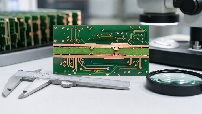

What is a double sided PCB?
Double-sided printed circuit boards have double-sided wiring,having the top and bottom floors. All surface treatments can be achieved, all types and colors of weld resistance layers, including matte and gloss. Double-sided printed circuit boards are mounted with conductive copper and components on both sides of the printed circuit boards so that the wires can cross each other. It results in higher density of circuit boards without point-to-point welding, making double-sided printed circuit boards is difficult, complex, and better using double-sided than single-sided printed circuit boards.

Two-layer PCB fabrication planned for plated interconnection and assembly access
Double-sided PCB manufacturing creates copper circuitry on both sides of a rigid board, normally connected by plated through holes and vias. A double-sided circuit board is often the lowest-complexity route when a single copper layer cannot provide enough routing, ground or component access. It should not be confused with a multilayer board: there are only two copper layers, so return paths, power distribution, component placement and soldering access require deliberate planning.
OrinewPCB can review the two-layer PCB fabrication package and continue the board into one-stop PCB assembly with 100% new and original components, SMT and through-hole operations, inspection and agreed testing. Coordinating the panel, finish, hole design and component sides helps avoid a board that is inexpensive to fabricate but awkward to assemble.
When should you choose Double-Sided PCB?
The correct route is the simplest construction that satisfies the released electrical, mechanical, thermal, compliance and assembly requirements. Use the comparison below to define why this board type is necessary before specifying details.
| Route | Use it when | Release decision |
|---|---|---|
| Single-sided PCB | The circuit is simple and all routing fits one copper side | Lowest complexity but limited routing and grounding |
| Double-sided PCB | Two copper sides and plated interconnection solve the layout | Balance routing, return paths and assembly access |
| Four-layer PCB | Dedicated power or ground planes and denser routing are needed | Use a defined multilayer stackup |
| Metal-core or special board | Thermal or material requirements dominate the design | Choose a construction from the functional requirement |
Double-Sided PCB design and DFM controls
The most useful DFM review checks the features that control fabrication and assembly risk, rather than comparing the design with a generic capability list.
Use vias to support the return path
A via is not only a routing connection; its placement can affect current return, grounding and assembly clearances.
Plan both component sides
Bottom-side components change paste printing, reflow, selective soldering, inspection and fixture access.
Define plated and non-plated holes
Mounting holes, slots and component leads must be identified correctly so plating and tolerances match the mechanical intent.
Choose the finish for the assembly route
Pad flatness, through-hole soldering, storage and contact use influence the surface-finish decision.
How the manufacturing route is reviewed
A reliable build keeps the requirement, material, fabrication data and acceptance evidence connected through the release process. The exact operations vary with construction, but the following gates should be explicit.
- Two-layer data review: Confirm top, bottom, mask, legend, outline and drill data from one revision.
- Drill and hole preparation: Create the released plated and non-plated features.
- Through-hole plating: Form the conductive connection between the two copper sides.
- Outer-layer patterning: Image and etch the top and bottom copper.
- Mask, legend and finish: Apply the released solder mask, markings and pad finish.
- Electrical and final checks: Verify connectivity and the agreed visual or dimensional characteristics.
Files to send for an engineering review
Every file should identify the same board revision. A complete package shortens clarification time and makes price, material and delivery assumptions visible before production.
| Input | Required detail | Decision supported |
|---|---|---|
| Fabrication data | Gerber, ODB++ or IPC-2581 plus NC drill and board outline | Layer interpretation, holes, profile and DFM review |
| Stackup and materials | Layer order, finished thickness, copper, material and approved-equivalent rules | Construction and material proposal |
| Special requirements | Impedance, mechanical, compliance, finish, marking or documentation needs | Process selection and quotation scope |
| Assembly package | BOM, CPL, assembly drawing, variants and substitution rules when PCBA is required | Original-part sourcing and assembly planning |
| Test and delivery | Acceptance method, required evidence, quantity and target delivery | Inspection, test and schedule basis |
When the release package is ready, share the fabrication files and assembly inputs for a combined engineering review. OrinewPCB can then identify open DFM, material, sourcing and test questions before confirming the quotation scope.
Double-Sided PCB in one-stop PCB assembly
A two-layer PCB can support one- or two-sided assembly, but each added bottom-side process changes fixtures, reflow or selective-soldering decisions. For a small assembled build, the prototype PCB assembly service can review the fabricated board, BOM, placement files and test expectations as one controlled first build.
Compare the two-layer route with a four-layer PCB, review the main PCB manufacturing service, and use turnkey PCB assembly when board fabrication and component sourcing should stay together.
Quality, cost and lead-time factors
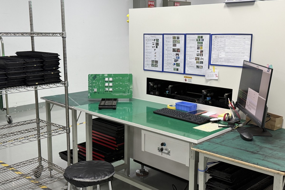
OrinewPCB uses a nine-step quality and test control framework that links release review, materials, fabrication, assembly and final verification. The actual inspection and test methods are selected for the board and customer-defined acceptance scope; not every board needs every method.
Double-sided PCB cost depends on board area, panel utilization, drill count, plated holes, copper weight, finish, quantity and electrical testing. Assembly cost may increase when components appear on both sides or when mixed SMT and through-hole operations require additional handling.
- Resolve missing or conflicting data before material is committed.
- Keep approved substitutions and evidence requirements in the released order.
- Confirm panel, tooling and assembly constraints together when PCBA is included.
- Plan delivery as early as practical after material, process and test inputs are reviewed.
Double-Sided PCB FAQ
What is a double-sided PCB?
It is a circuit board with copper patterns on the top and bottom sides, normally interconnected by plated through holes and vias.
Is a double-sided PCB the same as a two-layer PCB?
Yes, the terms are commonly used for a board with two copper layers. The finished construction and assembly sides should still be stated clearly.
When should I move from two layers to four layers?
Consider four layers when routing density, power distribution, EMC or controlled return paths cannot be handled reliably on two copper layers.
Can both sides of a double-sided PCB be assembled?
Yes. Two-sided assembly requires a process plan for paste printing, placement, soldering, fixtures and inspection on each side.
Plan the next build from one controlled data set
The board construction, component BOM, assembly revision and acceptance plan should describe the same product. This reduces supplier handoffs and makes engineering decisions easier to trace across prototypes, small-to-medium batches and high-mix production.
If the project is ready to move forward, provide the released PCB data, BOM, quantities and test requirements for the next-build review. The returned scope can address fabrication, 100% new and original component sourcing, assembly, testing and the earliest practical delivery plan together.