Clock/Timing
1. What are Clock and Timing ICs?
The Core Difference between Clock IC and Timing IC
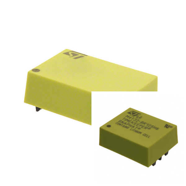
Clock IC (such as RTC chip) is mainly used to output stable clock signal and provide synchronization reference for processors, communication equipment, etc. Its core function is to generate accurate frequency signals through crystal frequency division.
Timing IC focuses on generating programmable time intervals or delay signals, usually integrating oscillator and counter, suitable for automation control, timing switch, and other scenarios.
The Role of Crystal Oscillators in Two Types of IC
Both rely on crystal oscillators as oscillation sources. Clock IC mostly uses 32.768kHz crystal (error ≤±20ppm) because of its high-frequency stability and low power consumption; timing IC can choose crystal or RC oscillation mode according to demand, the latter is lower in cost but poorer in accuracy.
2. What are Clock and Timing ICs Used for?
1) Clock IC
Synchronous Digital System: microcontroller, FPGA, and other occasions that require global clock synchronization.
Communication Equipment: timing control of the router, time synchronization of 5G base station.
Consumer Electronics: mobile phone real-time clock (RTC), low-power timing of smart wearable devices.
2) Timing IC
Industrial Control: Delay triggering of production line automation equipment, cyclic task management.
Home Appliances: LED flashing control, washing machine program timing.
Security System: sensor signal acquisition interval setting.
3. Common Faults and Solutions of Clock and Timing ICs
1) The Crystal Oscillator does not Oscillate
Cause: PCB wiring is too long/interference (such as cross-wires between crystal pins), crystal oscillator quality defects, improper capacitor matching.
Countermeasures: Optimize routing (shorten the path, avoid parallel signal lines), replace high-precision crystal oscillators, and adjust ground capacitance parameters.
2) Timing Error Accumulation
Cause: Crystal oscillator temperature drift (frequency is affected by temperature), power supply voltage fluctuations and aging effects.
Improvement: Use temperature-compensated crystal oscillators (TCXOs), add power supply filtering circuits, calibrate regularly, or select chips with automatic timing functions.
3) Timing Function Failure
Hardware Problems: Short circuit caused by residual solder flux and abnormal chip power supply.
Troubleshooting Steps: Clean PCB solder joints, measure power supply voltage stability, and replace spare chips for verification.
4. Selection and Maintenance Recommendations for Clock and Timing ICs
1) Key Selection Parameters
Clock IC: frequency stability (such as ±5ppm), power consumption (RTC often requires μA level), interface compatibility (I²C/SPI).
Timing IC: timing accuracy (error range), operating voltage range, output signal type (PWM/level).
2) Long-term Maintenance Measures
Avoid drastic changes in ambient temperature and humidity to prevent crystal oscillator parameter drift.
Check the battery voltage (if any) regularly to prevent RTC data loss.
Use redundant design (such as dual crystal backup) to improve the fault tolerance of high-reliability systems.