
SMT Tombstoning: Compare Both Ends Before Changing Reflow
Table of Conent
Table of Conent
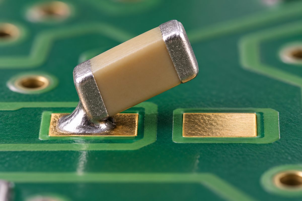
SMT tombstoning occurs when one end of a component lifts away from its intended solder connection during reflow. A small two-terminal passive may stand upright or tilt sharply, leaving an open connection. The visible defect is easy to recognize; the conditions that produced it are less obvious.
A useful investigation compares the two ends of the affected component through printing, placement, and heating. Do not begin by raising the oven temperature or changing every process setting. Preserve the evidence, identify the repeated imbalance, and test a correction against both the defect and the rest of the assembly.
Confirm the defect and preserve the original condition
Distinguish a raised termination from a component that is merely shifted, missing, or poorly wetted while still lying flat. Record the component reference, board revision, side, panel position, lot, and inspection stage. Take images before rework changes the joint geometry or removes the original paste and residue evidence.
Check whether the open connection is consistent with the observed geometry. A visual classification and an electrical failure record should refer to the same location. Avoid grouping every small-passive open circuit under the tombstoning label, because different failure mechanisms require different corrective actions.
Collect unaffected examples of the same footprint and component family. Comparing good and affected locations on the same build can be more informative than comparing the board with a generic defect photograph. Keep the component and material histories available so later findings can be traced to their actual production conditions.
Understand the two-end imbalance
Indium Corporation’s discussion of tombstoning mechanisms describes how unequal wetting forces can rotate a device and separate one end from its connection. Heating, deposit contact, geometry, and surface condition can all influence how the two terminations behave.
The engineering question is therefore not simply whether the board reached a target peak temperature. Ask whether the two ends encountered comparable conditions at the time solder wetting developed. A satisfactory overall oven setting can coexist with a local mismatch at one small component.
Treat the final appearance as evidence of an imbalance, not a unique diagnosis. The raised end does not by itself identify the wrong stencil aperture, a placement error, or a thermal problem. Build a testable explanation from the records associated with that exact location.
Compare printing evidence as a pair
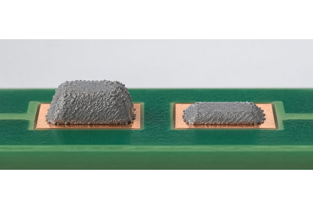
Review both paste deposits for the affected component together. Check their measured volume, height, area, and positional offset, along with the inspection program and its reference geometry. Two individually passing records can still warrant a paired review if the accepted limits do not address the relevant asymmetry.
The solder paste inspection guide explains how to use deposit measurements and process trends. Reconcile each measurement with the correct pad, stencil revision, board side, and component reference. An incorrect inspection model can make a comparison appear balanced or unbalanced for the wrong reason.
Look for repeatable patterns across panel instances and printing time. Compare the suspect apertures, stencil condition, cleaning history, and alignment with unaffected locations. A pattern emerging after several prints suggests a different investigation from a defect that occurs consistently at one design location.
Do not automatically reduce every deposit to suppress movement. Any aperture change must preserve acceptable solder-joint formation and remain compatible with the chosen paste and stencil process. Define what the proposed change is expected to improve and how its other effects will be checked.
Preparing a process review? submit the PCB and stencil outputs, BOM, affected references, paired paste-inspection records, quantities, and defect images for engineering and quotation review. Include the current revisions so the evidence can be matched to the intended assembly.
Check contact immediately after placement
Inspect whether both terminations overlap their intended deposits after placement. Review component offset, rotation, seating, and the relevant placement setup. A nominal coordinate in the program does not establish the component’s actual contact with the printed deposits.
Compare nozzle condition, component presentation, and placement settings where the evidence supports that investigation. Include changes in component supply or package dimensions. Review the actual device information rather than assuming parts with the same nominal electrical value have identical terminations or body geometry.
If deposits differ in height, ask whether the placed body is supported and contacting paste as intended. If the component is skewed, identify whether the mismatch came from printing, placement, or the footprint relationship. These conditions can interact, so retain the paired images and measurements.
A hypothetical example is one reference that repeatedly has a displaced print and a visibly off-center component before reflow. Correcting the print alignment and then checking placement gives a clearer trial than changing oven settings while the pre-reflow mismatch remains present.
Evaluate the local thermal context
Inspect the layout around each termination, including copper connections, nearby thermal mass, and differences between panel locations. Indium’s tombstoning-reduction guidance identifies unequal thermal conditions as one contributor. Use the layout to develop a hypothesis, then seek process evidence rather than declaring copper area alone to be the cause.
The reflow soldering process guide provides broader context. Review a measured profile from a representative assembly under the relevant loading and conveyor conditions. Oven zone setpoints are controls, not measurements of every solder location.
Work with the process engineer to choose meaningful measurement sites and attachment methods. Small-component measurements can be intrusive, so document limitations and repeatability. Record the relationship between the measured evidence and the location actually showing the defect.
A revised heating approach must remain within the applicable paste, component, board, and process requirements. Check other locations with different thermal mass, not just the affected passive. A local improvement is not acceptable if it introduces incomplete joints or excessive thermal exposure elsewhere.
Keep material and atmosphere changes controlled
Record the paste product and lot, component finish and lot, board finish, storage history, and handling conditions. Differences in solderability or material condition can change the comparison between terminations. A material substitution should be evaluated as a process change, not hidden inside an unrecorded trial.
Kester’s soldering-process FAQ emphasizes the relationship between flux chemistry, surface finishes, thermal compatibility, and atmosphere. Use the current product documentation and supplier advice for the selected materials. Do not treat one published profile or alloy example as a universal recipe.
Atmosphere changes can alter wetting behavior. Confirm why the current atmosphere was selected and what other joints depend on it before making a change. The trial must evaluate the complete assembly requirements, not only whether one defect disappears in a small sample.
For a supplier or material change, send the approved BOM, proposed component or paste changes, board finish, process requirements, quantities, and affected-location evidence for a manufacturing and quotation review. Identify which substitutions need engineering approval.
Run a trial that can distinguish explanations
Write the proposed cause in a form that can be tested. For example, an asymmetric print at a particular footprint should have a measurable pre-reflow signature. A placement hypothesis should predict a contact or orientation difference. A thermal hypothesis should be consistent with the layout and measured process behavior.
Set a baseline with defined inspection criteria, build conditions, and traceable records. Change one clearly scoped factor at a time where practical. If several factors must change together, document that limitation instead of claiming the trial isolated one cause.
Check the affected reference and neighboring joints before and after reflow. Include other panel positions, relevant component families, and the accepted test requirements. Record actual observations and the size of the evaluated sample; do not turn a short successful trial into a permanent yield guarantee.
Separate containment from permanent prevention
Sorting or rework can contain an affected lot, but it does not prove that the next build is protected. Preserve the original failure records and define the approved disposition separately from the corrective-action trial. Use the applicable product requirements and authorized rework procedure for acceptance decisions.
Discuss the evidence package with the SMT assembly service team before a repeat run. Agree on the current design, material, stencil, placement, and process revisions. A general service description does not establish a particular profile, acceptance class, or guaranteed defect rate.
When a correction is accepted, update the controlled files and production instructions that actually changed. Identify the approved inspection and verification steps. Keep trial records linked to the release so a later material, layout, or program change does not silently remove the corrective condition.
Pre-release checklist
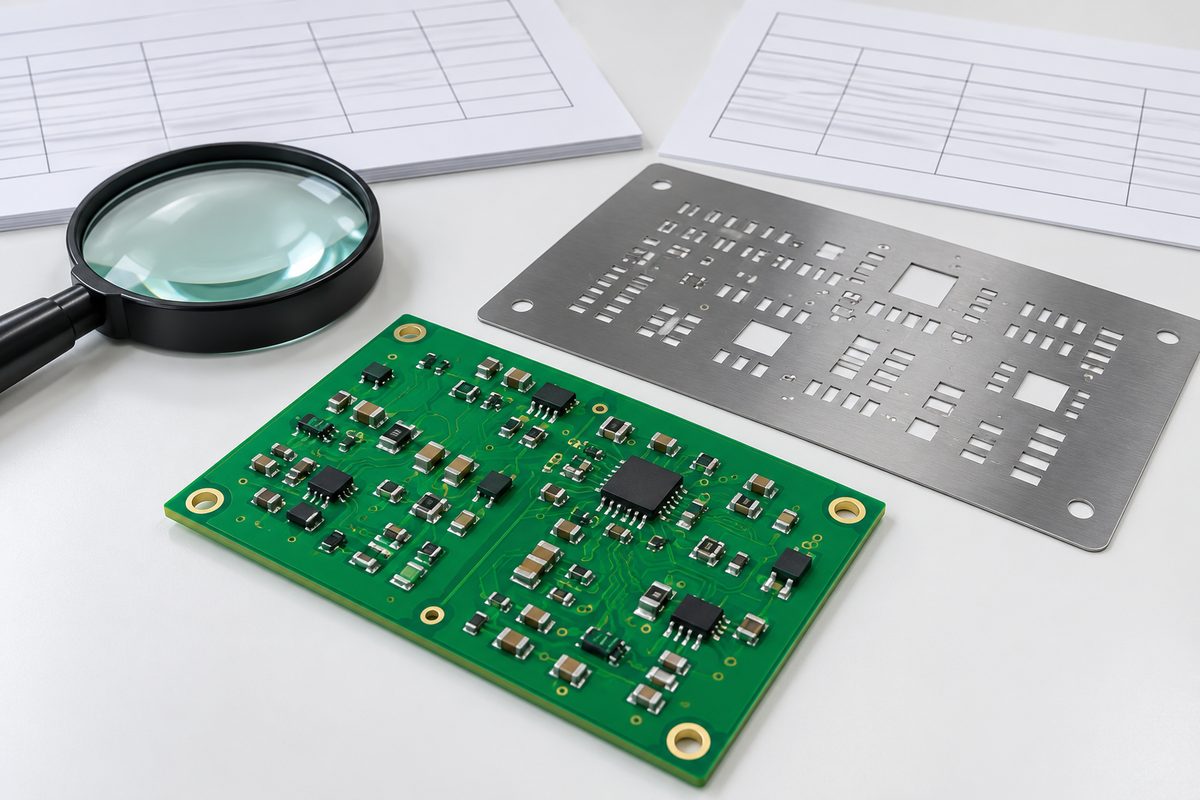
- Confirm the defect classification and preserve pre-rework evidence.
- Compare both deposits and actual component contact before reflow.
- Review local geometry, thermal evidence, materials, and recent changes.
- Define a testable cause and a scoped verification trial.
- Check the complete assembly for unintended effects.
- Separate lot disposition from permanent corrective-action approval.
SMT tombstoning deserves a paired investigation across the process. Compare both ends, test the explanation, and preserve the accepted conditions in the production release.
Planning the next build? submit the fabrication files, BOM, stencil and placement revisions, defect evidence, testing requirements, and quantities for engineering review and quotation. Include the accepted correction and any unresolved exceptions.
Latest Blog

Contact Info
Phone: +86-755-82882936
Email: [email protected]
WhatsApp: +86-13570802455
Wechat: +86-13570802455
Address: 2nd floor,D Bldg.,Electric Link Technology Bldg.,Gongming,Guangming New Dist.,518106 Shenzhen, China