
Pick-and-Place Files: Origins, Rotations, and Assembly Checks
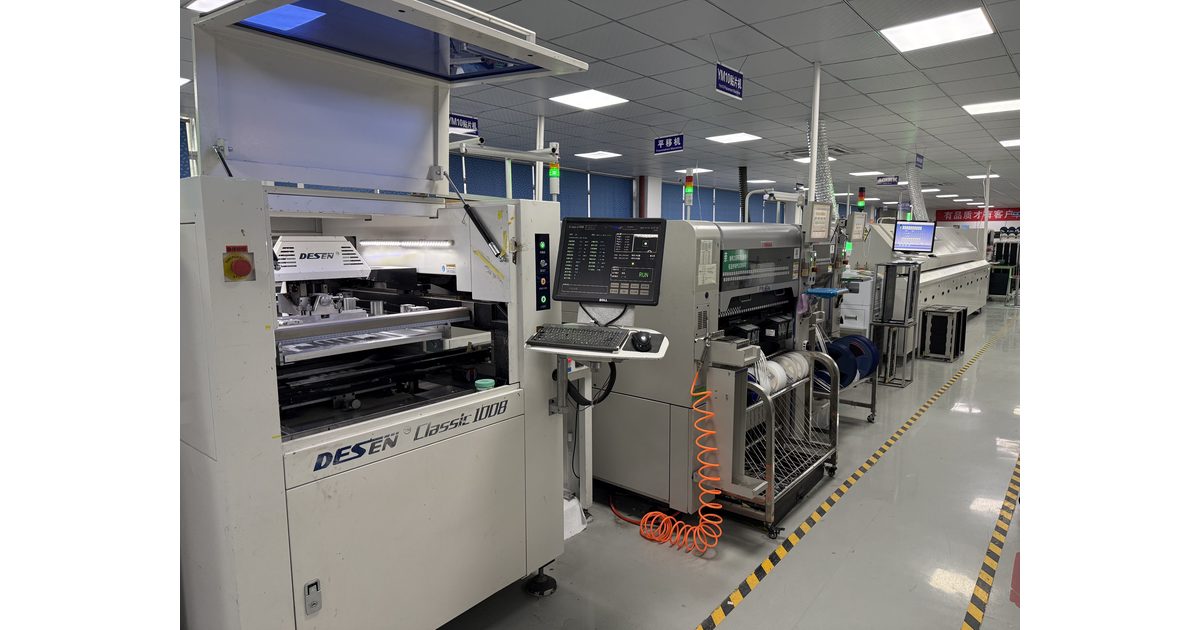
Table of Conent
Table of Conent
A pick-and-place file tells the assembly team where components belong, which side of the board they occupy, and how they are oriented. It is also called a placement, position, or centroid file. The file supports assembly programming, but it does not replace the BOM, package documentation, or assembly drawing.
The common release problem is not an unreadable spreadsheet. It is a readable file interpreted with the wrong origin, units, reference point, or bottom-side convention. A useful review checks those meanings before comparing rows. This guide explains how to deliver placement data that can be reconciled with the actual design and assembly variant.
Define the minimum information and its meaning
A typical placement record identifies the component reference, X and Y location, board side, and rotation. Footprint or package information and a part description can help the assembler reconcile the record with other files. Confirm the requested columns and format with the selected assembly provider instead of assuming every CSV template is interchangeable.
Altium’s assembly-output documentation distinguishes component-center coordinates, footprint-reference coordinates, and pad-one coordinates. Those locations can differ, especially for asymmetric footprints. A column labeled “X” is incomplete unless its reference-point meaning is understood.
Keep the component designator as a stable identifier across the BOM, placement file, and assembly drawing. A value such as “10k” can describe several resistors, while R17 identifies one location. Do not use a generic value or footprint name as a replacement for the designator when matching production records.
Freeze the origin and units before exporting
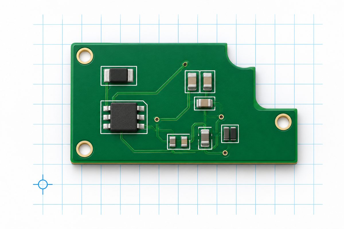
Choose the agreed coordinate origin and document it on the board or assembly reference drawing. Record the units and export settings with the release package. Changing the origin after export can leave a file that looks internally consistent while no longer matching the production artwork.
The KiCad 9 placement-file documentation describes options for units, the drill/place origin, and bottom-side coordinate handling. These are export choices, not requirements that every assembler uses. Confirm how the receiving workflow expects the data to be interpreted.
Check a few widely separated components against the board outline. A common displacement can indicate an origin mismatch, while a consistent size scaling can indicate a unit mismatch. These are investigation clues, not a substitute for reading the file header and export configuration.
Do not repair a suspected origin problem by manually changing a handful of rows. Establish the intended transformation, regenerate or systematically correct the file through a controlled process, and verify the full result. Preserve the original export so the correction can be audited.
Do not confuse the file origin with fiducial alignment
The coordinate origin describes the design data. Fiducials provide physical references that can support recognition and alignment in assembly equipment. They are related parts of the workflow, but adding fiducials does not automatically resolve a misunderstood coordinate system.
The PCB fiducial-mark guide explains board and panel references. Agree on whether the file describes one board image or an entire panel, and how the assembly provider will use the physical references. A single-board origin should not be silently treated as the panel origin.
If a panel contains repeated circuits, clarify whether the supplier will replicate the single-board placement data or expects panel-expanded records. Define instance naming, spacing, and any rotated images. Sending both forms without stating which is authoritative creates another opportunity for programming the wrong locations.
Confirm the bottom-side viewing convention
A bottom-side placement can be represented using different coordinate and viewing conventions. A CAD exporter may offer a sign change or other side-specific option. Do not automatically negate X, negate Y, or mirror the entire file because a preview appears reversed.
State the chosen convention and verify it against an asymmetric feature. A connector near one corner, a notch, or another unmistakable reference can reveal a mirror interpretation that a symmetric component array might conceal. Compare the exported side with the assembly drawing using the same viewing direction.
Keep the layer names unambiguous. A numeric code, “front,” “back,” “top,” and “bottom” may be interpreted differently by import tools unless their mapping is defined. If the supplier requests separate side files, ensure each contains the intended records and that no component has been assigned to both by mistake.
Have an unresolved import convention? send the placement export, origin and units definition, BOM, board outline, and both assembly-side drawings for engineering review. Include the CAD version and export choices so the data interpretation can be checked before quotation.
Treat rotation as a reference-dependent value
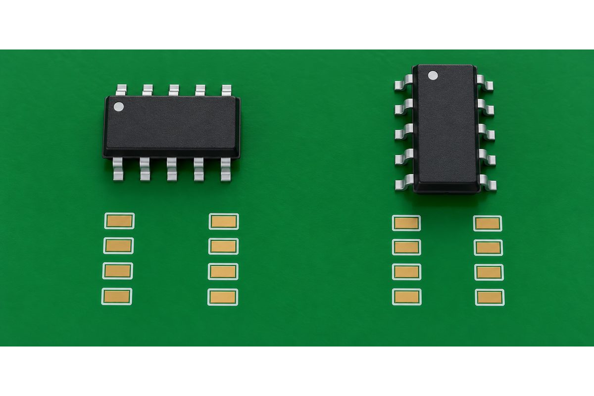
A rotation value needs a zero-degree orientation and a direction convention. The footprint library establishes an orientation, while the assembly provider’s package model may establish another. A component placed at zero degrees in the design does not necessarily correspond to zero degrees in the receiving machine library.
Use pin-one and polarity information to verify the result. Check representative ICs, diodes, polarized capacitors, and asymmetric connectors against their package documentation and the assembly drawing. A body outline alone may not reveal a reversed device.
The silkscreen and orientation-marking guide provides related context for physical markings. Silkscreen is useful corroboration, but it should not override a conflicting footprint pin assignment or package drawing. Resolve the design conflict instead of changing a rotation value to make one preview look correct.
Do not add a blanket rotation offset to every component without verifying that the same reference mismatch applies to each package and side. A correction appropriate for one footprint family can reverse another. Record any approved mapping and validate its scope before it enters production.
Reconcile the placement list with the assembly variant
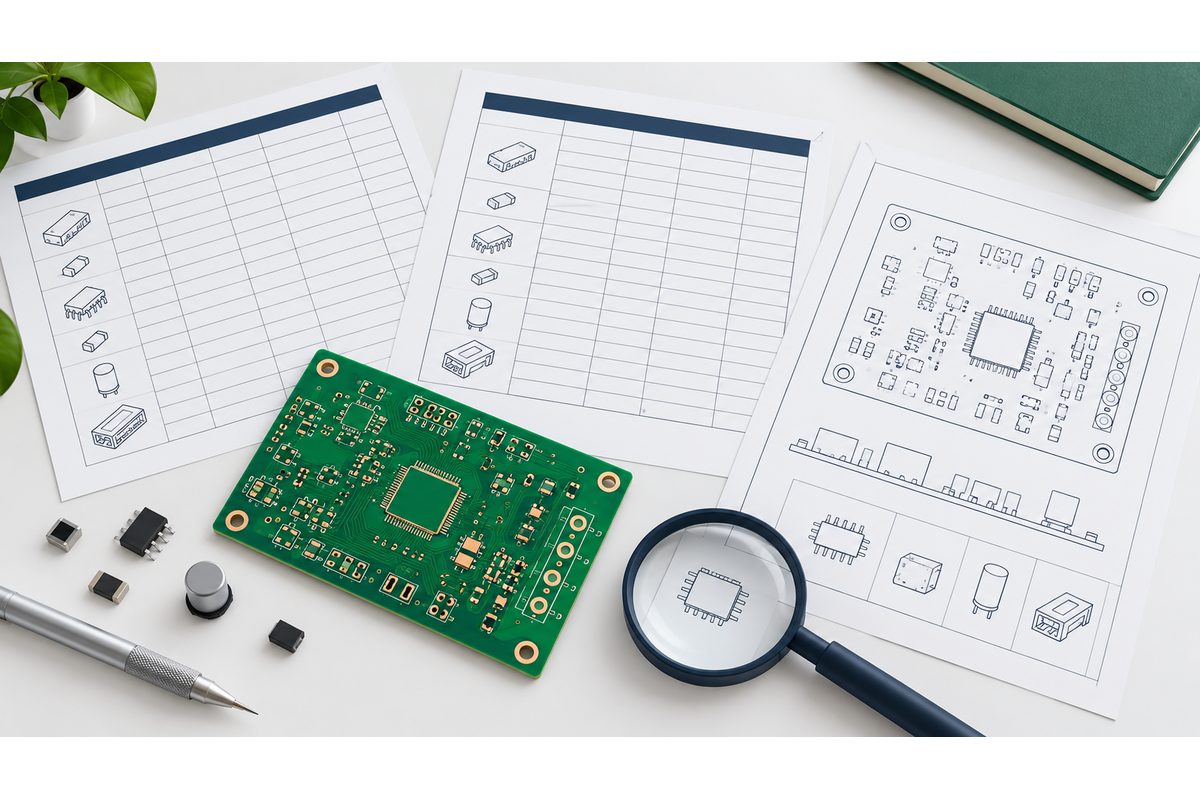
Compare populated component references with the BOM and variant definition. Identify missing records, duplicate references, incorrect board sides, and entries excluded by footprint or component filters. A successful export does not establish that the correct subset was selected.
Agree on how do-not-populate items are represented. Some workflows want them omitted from placement data; others retain them with an explicit status. Keep the BOM, drawing, and placement file consistent with the accepted approach. An unpopulated resistor should not be indistinguishable from a part accidentally omitted by an export filter.
Through-hole parts, mechanical objects, fiducials, and virtual graphics may need different handling. Confirm the provider’s requirements instead of deleting everything that is not a conventional SMD component. The file’s purpose is to support the agreed assembly process, not to maximize or minimize its row count.
For mixed or variant builds, submit the BOM variants, placement files, population exclusions, quantities, and special assembly notes for a manufacturing and quotation review. Identify which configuration is to be built so the programming scope is clear.
Check the exported file, not just the CAD view
Open the actual delivery file and inspect its header, columns, units, side labels, and representative rows. Check that decimal formatting, delimiters, quoted fields, and any unit suffixes will be accepted by the receiving workflow. A spreadsheet display can hide text fields or reinterpret values during editing.
Use a structured cross-check rather than reading random rows. Start with a component near the origin, one near the opposite edge, a bottom-side part, and an orientation-sensitive device. Then reconcile the complete populated reference set with the BOM. These samples test geometry assumptions; they do not replace the full reference comparison.
As a hypothetical example, matching all reference names but seeing every part displaced by the same amount suggests checking the origin before editing footprints. Matching positions but seeing one package family rotated differently suggests checking its library orientation. A mirrored pattern on only one side suggests reviewing the side convention. Each pattern narrows the investigation without proving the cause.
Deliver one controlled assembly package
Export the placement data, BOM, board fabrication files, and assembly drawings from one released design and variant. Include the board identifier, revision, units, origin, viewing conventions, and unresolved exceptions in a short release note. Do not leave the supplier to infer the authoritative file from several similarly named exports.
Review the requested data package with the SMT assembly service team for the actual project. File review and machine programming still require project-specific reconciliation; a general service page does not establish one universal import template or package-library convention.
When a component, footprint, origin, panel, or variant changes, regenerate the affected files and repeat the relevant checks. Preserve accepted programming clarifications with the revision so repeat orders do not inherit an unexplained manual correction.
Pre-release checklist
- Confirm the requested placement columns, format, units, and coordinate reference point.
- Document the origin, board-versus-panel scope, and top/bottom viewing convention.
- Verify rotation using package-specific pin-one and polarity information.
- Reconcile all populated references and exclusions with the BOM variant.
- Inspect the actual exported file and representative geometry cases.
- Freeze one revision and preserve approved import or library mappings.
A reliable pick-and-place file is more than a list of coordinates. It is a clearly defined interpretation of the released assembly design. Matching identifiers, geometry conventions, and package orientation gives the assembler a sound basis for programming and first-article checks.
Ready for the assembly run? submit the final placement files, BOM, fabrication package, assembly drawings, quantities, and convention notes for engineering review and quotation. Resolve ambiguous origins, sides, and rotations before production release.
Latest Blog
Contact Info
Phone: +86-755-82882936
Email: [email protected]
WhatsApp: +86-13570802455
Wechat: +86-13570802455
Address: 2nd floor,D Bldg.,Electric Link Technology Bldg.,Gongming,Guangming New Dist.,518106 Shenzhen, China