
Component Packaging: Reels, Cut Tape, Trays, and Tubes
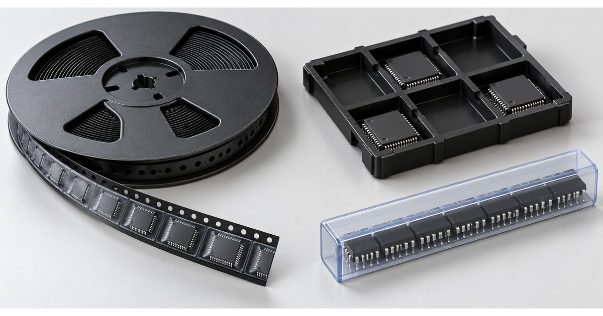
Table of Conent
Table of Conent
Component packaging affects how parts reach the assembly machine, how their identity is preserved, and how much preparation a production kit needs. Tape-and-reel, cut tape, trays, and tubes describe delivery carriers. They are different from electrical package names such as QFN, SOIC, or BGA.
The lowest purchase quantity is not always the lowest-effort assembly option. Confirm the receiving team’s accepted carrier formats before ordering or shipping parts. A complete packaging review connects the exact manufacturer part number, quantity, orientation, handling requirements, and planned assembly process.
Separate the device package from its delivery carrier
The device package defines the component body and terminals. The carrier organizes those devices for transport, storage, and feeding. One device may be offered in more than one delivery format, but availability and ordering codes depend on the manufacturer and distributor.
Check the full orderable part number, not only the base device name. A suffix can identify a packaging option or another product distinction. Confirm its meaning in the current supplier information rather than assuming the same suffix convention applies across brands.
Keep the manufacturer part number and distributor ordering identifier in separate fields when building the procurement list. The assembly BOM should still identify the approved device. The delivery record should explain which carrier and quantity will arrive for that BOM line.
Understand tape-and-reel as a feeding system
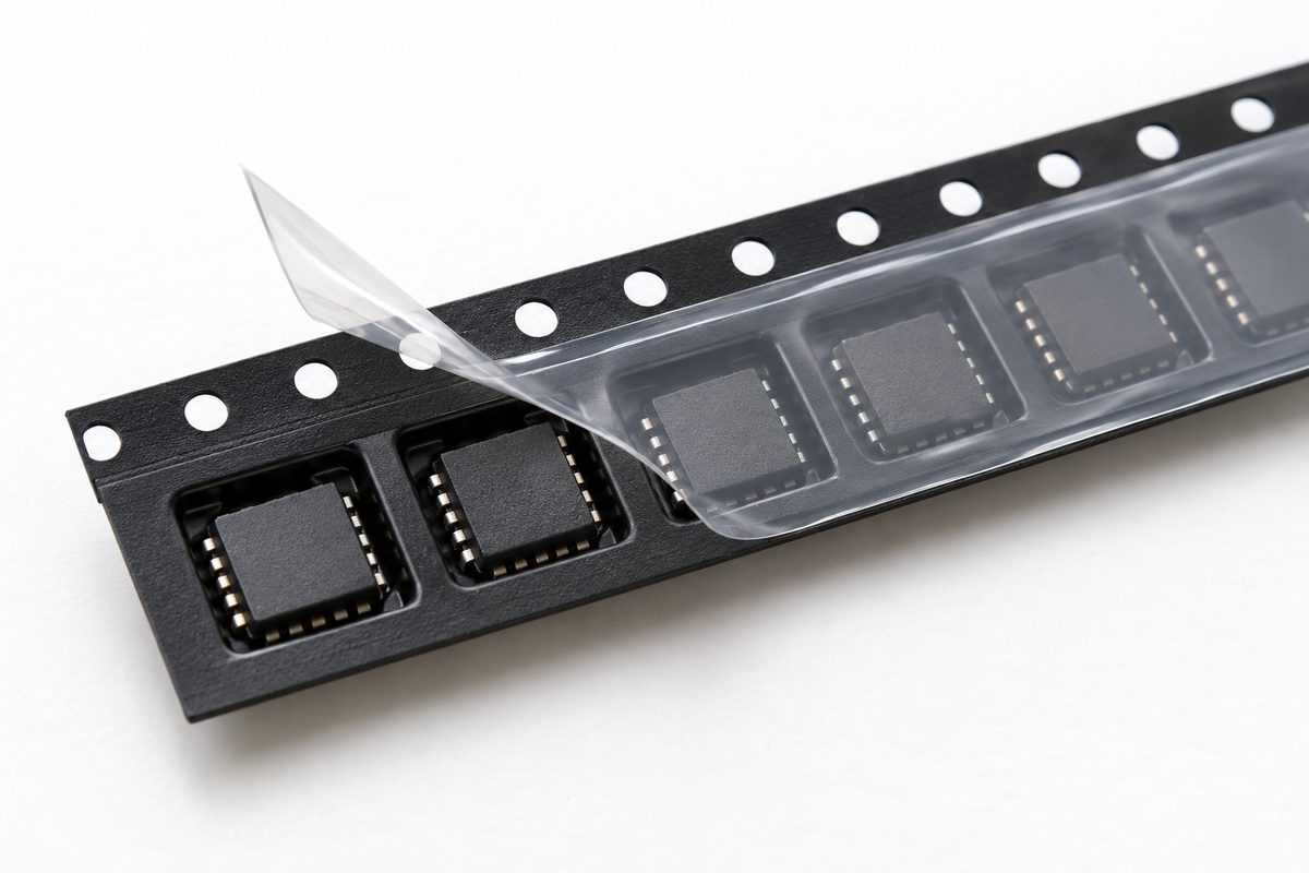
Tape-and-reel uses a carrier with repeated pockets and a cover that retains individual components. Texas Instruments’ industrial packaging report describes carrier dimensions and orientation considerations. The practical lesson is to verify the specific packaging drawing, not merely to request “a reel.”
Confirm tape width, pocket pitch, pocket geometry, reel format, and component orientation with the receiving team. These details need to match the available feeder and setup. A component fitting inside a pocket does not establish that the entire carrier is compatible with the selected production equipment.
A full manufacturer reel may support continuous feeding and clear original labeling, but its quantity may exceed the immediate build requirement. Discuss remaining inventory ownership, storage, and return arrangements before purchasing a large quantity solely for feeding convenience.
Distinguish cut tape from a prepared custom reel
Cut tape is a shorter section of component-bearing tape rather than a complete production reel. Confirm whether the ordered quantity will arrive as one continuous strip or multiple sections. The receiving workflow must account for strip length, cover retention, and loading requirements.
DigiKey’s custom-reel explanation describes adding leader and trailer sections to a continuous cut-tape quantity. This is a supplier-specific service example, not a statement that every cut-tape item can be reeled or that every assembler accepts the same preparation.
Ask whether a supplied custom reel includes the necessary leader, trailer, splice construction, and identifying label for the intended workflow. Confirm service eligibility and the resulting carrier specifications with the supplier. Do not infer automation compatibility from a distributor catalog icon alone.
Short strips may be practical for an approved prototype workflow. They can also require extra setup or handling compared with a prepared reel. Agree on the accepted minimum presentation and any preparation before delivery, rather than sending loose sections and expecting the assembler to improvise.
Planning a customer-supplied kit? submit the approved BOM, component quantities, proposed carrier formats, supplier packaging details, and build quantity for engineering and quotation review. Identify short strips or other exceptions before shipping.
Review trays and tubes with the assembly team
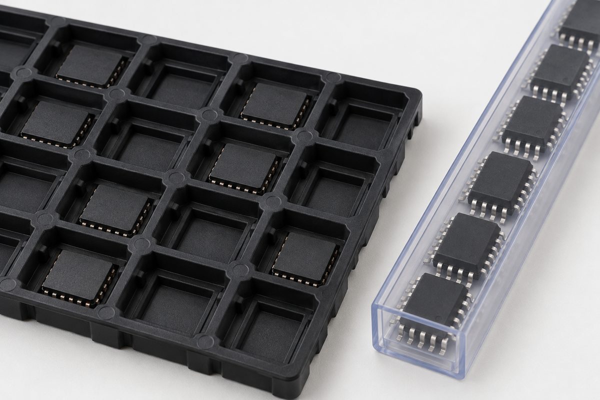
A tray supports devices in individual locations, while a tube keeps a sequence of components in a constrained channel. Both can be appropriate delivery formats when accepted by the production workflow. Neither should be treated as a universal substitute for a tape feeder.
For trays, check the approved tray design, pocket arrangement, component orientation, and handling constraints. Keep the device identification associated with each tray or clearly separated tray group. Mixing similar-looking devices in one unmarked tray creates an avoidable receiving and setup problem.
For tubes, preserve the supplied end retention and orientation information. Check the component family and tube geometry against the receiving setup. A damaged or unsuitable tube can complicate feeding even when the components themselves are the correct part number.
If a carrier transfer is proposed, define who performs it and how identity, orientation, quantity, and handling protection are maintained. Confirm the resulting format before approving the transfer. Repackaging is a controlled handling operation, not simply moving parts into a convenient container.
Verify carrier orientation separately from board rotation
Incoming carrier orientation and the rotation in the placement program describe different relationships. The carrier presents a component to the machine. The board data describes the required position and orientation on the assembly. The setup must reconcile both with the component’s pin-one or polarity information.
The placement-data and orientation guide explains why zero-degree definitions need interpretation. Use the exact device package drawing, incoming carrier information, and assembly drawing to check orientation-sensitive parts. A generic footprint name is not enough.
Record any approved setup mapping with the relevant revision. Recheck it when the approved device or delivery format changes. A supply change from one carrier to another should not silently inherit an orientation assumption from the previous kit.
Preserve ESD and moisture controls
The mechanical carrier is only one part of protection. Determine the device-specific electrostatic and moisture-sensitive handling requirements from manufacturer information and the supplied labels. Do not decide compliance from carrier color, a silver bag, or the fact that parts were delivered on a reel.
The moisture-sensitive component handling guide provides related workflow context. Keep the required exposure history and packaging information with the devices through receiving and preparation. Opening or repackaging can change the handling status that production needs to evaluate.
Do not bake components or their carriers using a generic internet temperature. Any drying procedure must fit the device, carrier materials, and applicable handling requirements. Ask for review when moisture history is incomplete instead of presenting an unknown kit as ready for immediate reflow.
Keep ESD-sensitive handling within the approved receiving and preparation process. If packaging is damaged, quarantine and assess the affected line item according to the agreed procedure. Replacing a bag does not by itself establish that the parts remained protected.
Plan quantity without inventing a universal allowance
Start with the populated quantity per board, the build quantity, and the selected BOM variant. Then ask the assembler to define any additional quantity needed for setup, feeding, inspection, or expected process handling. The allowance depends on the actual part and workflow, not one percentage for every line item.
Count populated references rather than relying on a generic board total. Similar parts can have different placement counts between variants. Document exclusions and substitutions so receiving personnel do not mistake a deliberate omission for an incomplete kit.
Record whether delivered quantities are distributed across multiple strips, reels, trays, or tubes. A line item may have enough total pieces but still require an agreed handling plan. Preserve the relationship between each carrier, its label, and its quantity.
For a purchasing decision, send the BOM variants, supplier carrier options, build quantities, available inventory, and handling exceptions for a manufacturing and quotation review. This allows the delivery plan to be evaluated alongside the assembly requirement.
Build a receiving package that can be reconciled
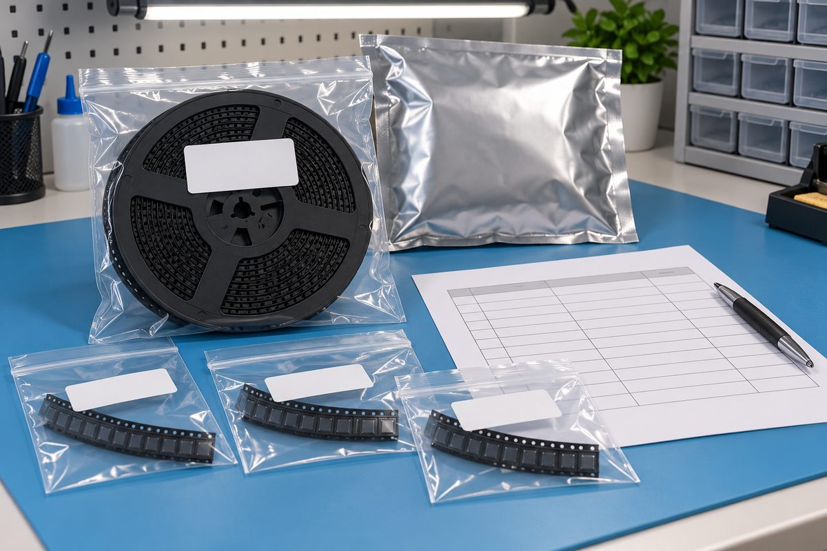
Provide a packing list that maps each container to its BOM line and exact part number. Include quantities and the available lot or date-code information without combining unlike devices under a shared label. Identify approved alternatives distinctly so they are not treated as uncontrolled substitutions.
As a hypothetical example, two visually identical capacitor strips can have different electrical values. Keeping each strip labeled and linked to its own BOM line prevents an appearance-based sorting decision. If their identity becomes uncertain, separate them for resolution rather than guessing from body size.
Discuss the kit with the SMT assembly service team before shipment. Confirm accepted carriers, preparation responsibility, handling records, and any unresolved quantity issues. A general service page does not establish acceptance of every tube, tray, strip, or custom reel.
Preserve receiving discrepancies and their approved resolution with the build record. Do not remove supplier labels before the required information has been captured and reconciled. Return or remaining-inventory records should keep the same identity trail as the incoming kit.
Pre-release checklist
- Confirm the exact device and orderable packaging identifiers.
- Check accepted carrier dimensions and incoming orientation.
- Resolve short strips, multiple sections, and carrier transfers.
- Maintain required ESD protection and moisture-exposure information.
- Agree on build quantities and project-specific extra parts.
- Map every container to a labeled, traceable BOM line.
Good component packaging planning reduces ambiguity between purchasing and production. Select an accepted carrier, preserve identity and handling history, and reconcile the complete kit before the assembly run.
Ready to release a build? submit the fabrication files, approved BOM, placement data, quantities, carrier list, and handling notes for engineering review and quotation. Include exceptions that still need agreement.
Latest Blog

Contact Info
Phone: +86-755-82882936
Email: [email protected]
WhatsApp: +86-13570802455
Wechat: +86-13570802455
Address: 2nd floor,D Bldg.,Electric Link Technology Bldg.,Gongming,Guangming New Dist.,518106 Shenzhen, China