
Solder Balls and Beads: Evidence, Prevention, and Disposition
Table of Conent
Table of Conent
Unintended solder balls and beads are separate solder deposits left outside the intended joints on an assembly. They deserve more than a cosmetic judgment: their location, attachment, and potential movement can matter to the product. First document what is present, then separate the lot-disposition decision from the process investigation.
This guide focuses on reflowed SMT assemblies. It does not cover intended BGA solder spheres, hand-soldering behavior on an iron tip, or wave-soldering spatter. Those situations need different evidence. A useful review connects the observed deposits with printing, placement, material condition, and the measured thermal process.
Describe the finding before naming the cause
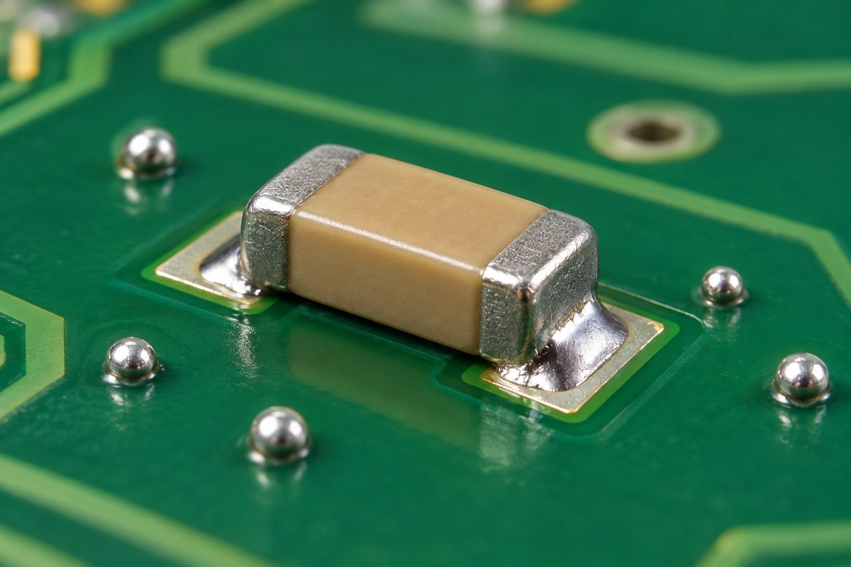
Record whether the observation is a field of small isolated spheres, a localized rounded deposit beside a component, or material associated with an intended joint. Teams may use “balling” and “beading” differently. Keep images and a clear location description with the defect name so the investigation does not depend on terminology alone.
Distinguish separate deposits from solder bridges, incomplete joint coalescence, and normal joint geometry. A bridge is an unintended connection between conductors. A rounded particle on solder mask is a different observation, even if the same print problem could contribute to both.
Do not assign a cause from one magnified photograph. A final sphere does not reveal whether material was misplaced before reflow, squeezed from beneath a device, or failed to join the intended deposit. Preserve the affected board and compare it with pre-reflow evidence where available.
Keep a location-based record
Map findings to the component reference, side, board and stencil revision, panel instance, lot, and inspection stage. Include views that show the relationship to nearby conductors, not only a tightly cropped particle. Record whether the observation was made before or after cleaning, handling, or rework.
Use the approved inspection method to evaluate size and attachment when those are relevant to disposition. Do not intentionally disturb particles before the original condition has been recorded. Any examination that moves material should be authorized and documented so later reviewers know the evidence changed.
Compare affected and unaffected sites from the same build. A repeated deposit beside the same component family suggests a different investigation from random material across many unrelated locations. Also check whether findings cluster by panel position, process time, or a particular material change.
Make disposition a separate decision
The quality team should apply the contracted workmanship requirements, applicable standard revision, product class when specified, and customer-specific criteria. A generic online photograph or particle-count rule is not a substitute for those requirements. This article does not supply universal IPC-A-610 size, count, or spacing thresholds.
Consider the actual location and product environment through the authorized review. A particle outside an immediate conductor gap should not automatically be declared harmless, and a visible rounded deposit should not automatically trigger the same action on every product. The decision needs the applicable requirements and documented evidence.
Record the chosen disposition: further evaluation, approved cleaning or rework, rejection, or another authorized action. Preserve the reason and verification steps. Passing one electrical test after handling does not by itself establish that all loose or inaccessible material has been addressed.
Need a documented review? submit defect images, location maps, assembly files, applicable acceptance requirements, quantities, and inspection history for engineering and quotation review. Identify whether you need process investigation, lot evaluation, or a new-build plan.
Use the printed board to test the first explanation
Inspect the intended deposits and surrounding mask before placement. Look for displaced paste, smears, unintended transfer, and differences between suspect and unaffected apertures. Confirm the stencil and board registration before treating a final deposit as a paste-chemistry problem.
The paste-inspection measurements and trends guide provides useful context for volume, height, area, and offset evidence. Reconcile inspection records with the actual aperture model and component reference. A passing program can miss material outside its reviewed regions.
Check whether the finding develops across printing time or appears immediately at one recurring geometry. Review stencil condition, cleaning records, transfer consistency, and board support where the evidence points to those factors. Do not adjust every printer setting because the final particles look similar.
If the proposed correction changes an aperture, compare its effect on the intended joint as well as the unwanted deposit. Reducing paste indiscriminately can create insufficient solder or other assembly problems. State the expected mechanism and the joint checks that must still pass.
Review placement and under-body conditions
A localized deposit beside a low-clearance component warrants checking what happened when the device contacted the paste. Compare the footprint, aperture shape, printed location, actual placement, and package geometry. Investigate whether material was moved toward a location where it could remain separate after reflow.
Use pre-reflow views and the relevant placement records rather than inferring displacement solely from the final bead. Include body dimensions and terminal geometry for the actual approved part. An alternative component with the same electrical function can change the mechanical relationship to the print.
A hypothetical example is a rounded deposit repeatedly found beside the center of one passive body. If pre-reflow evidence shows paste displaced into that region, a scoped print or placement trial is more informative than changing oven temperatures without addressing the local condition.
Reconcile paste condition and exposure history
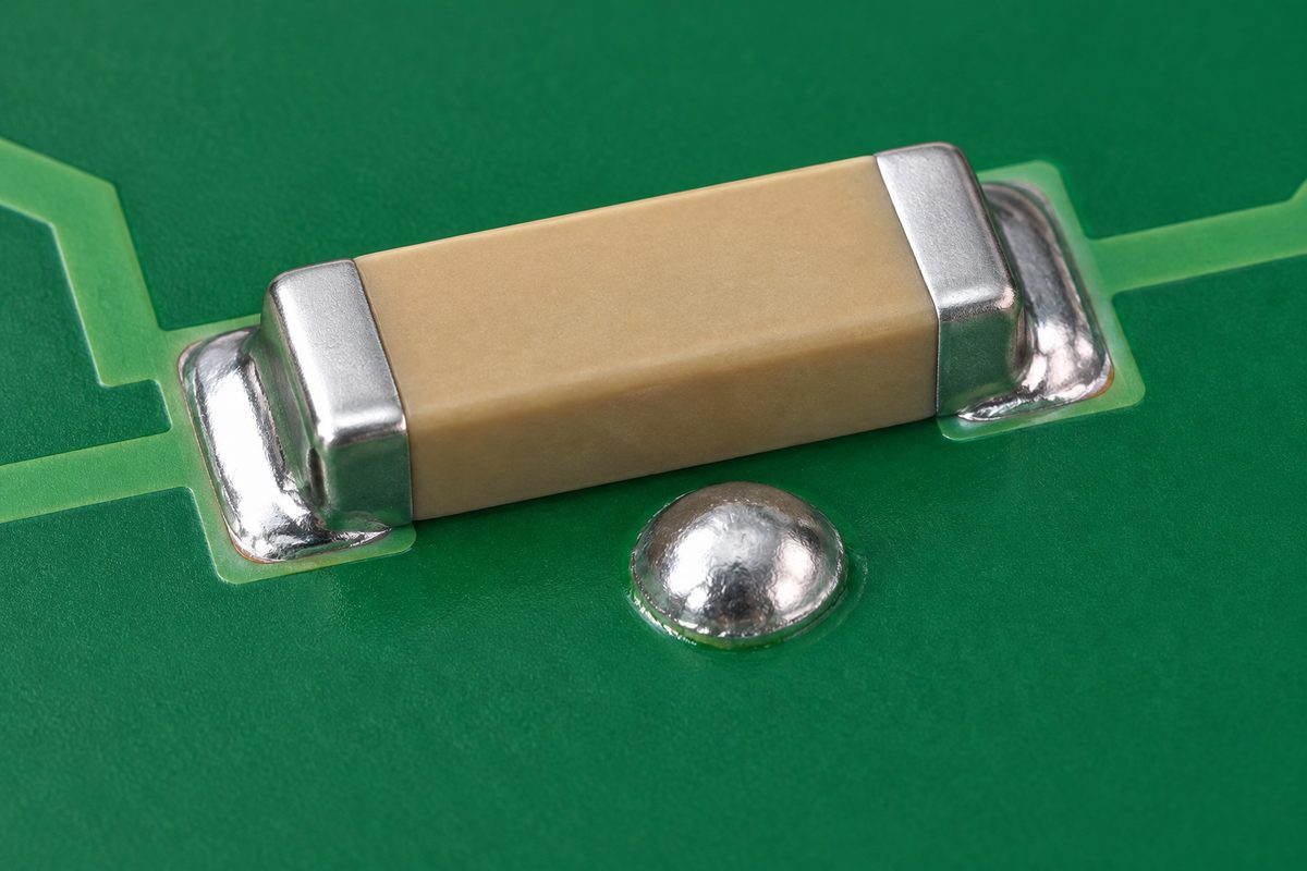
Keep the exact paste product, lot, storage history, opening time, working exposure, and any reuse practice available. The solder-paste storage and handling guide explains why those records should follow the actual product instructions instead of one universal schedule.
Kester’s historical SMT process tips connect paste handling and environmental exposure with process behavior. Use that background to frame questions, not to copy its older time, temperature, or humidity examples into a current production specification.
If the history is unknown, identify that gap and ask the material supplier how to evaluate the paste. Do not add solvent, fresh flux, or another paste to make the material appear usable unless an approved product-specific procedure permits it. Appearance alone does not establish retained process performance.
Also review board and component surface condition when wetting is in question. Keep contamination or solderability concerns distinct from a print-placement hypothesis. Different evidence may require separate investigations even when the final assembly shows several defect types.
Use measured thermal evidence
Indium Corporation’s reflow-defect discussion identifies incomplete wetting, deposit quantity, and heating behavior as relevant to solder balling. These are possible contributors, not proof of the cause on a specific board.
Review a measured profile from a representative assembly with the current paste, loading, and conveyor conditions. Confirm how the measurements relate to affected locations. Oven settings and a paste supplier’s example graph do not establish the thermal history of every deposit.
Any profile trial must stay within the applicable component, board, and paste requirements. Evaluate intended joint formation across the assembly and relevant board sides. Making scattered deposits disappear while weakening another joint is not a successful process correction.
For a trial build, send the PCB and stencil outputs, approved BOM, paste details, measured profile, affected references, quantities, and trial objectives for a manufacturing and quotation review. Include the constraints that a proposed change must preserve.
Validate the correction before the next release
Define the baseline and the inspection coverage before changing the process. State what the hypothesis predicts and collect evidence at the relevant stage. A print correction should have an observable print result; a material or thermal change needs a different verification plan. Keep the inspection lighting, magnification, and reviewed regions consistent between trial conditions, or document differences that could change the apparent finding count.
Change one clearly scoped factor at a time where practical. If several changes are necessary together, document that the trial cannot isolate their individual effects. Compare actual observations across affected references, panel positions, and other sensitive joints instead of checking only one cleaned board.
Discuss the complete evidence package with the SMT assembly service team. Confirm the project-specific process, inspection, acceptance, and deliverable requirements rather than assuming a general service includes a particular defect-investigation method.
Keep approved lot disposition and preventive action in separate records. Cleaning a lot can resolve the immediate material condition without preventing recurrence. Once a correction is accepted, update the actual stencil, material, program, or process revision and preserve its verification record.
Pre-release checklist
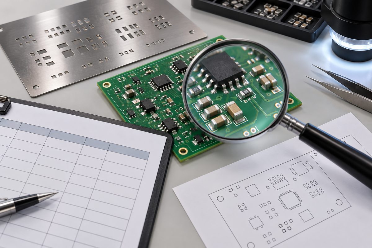
- Classify the observation and preserve original location evidence.
- Apply the actual product requirements through authorized quality review.
- Compare print, placement, material, and thermal evidence.
- State a testable explanation and a scoped trial.
- Verify intended joints and inspect relevant locations after correction.
- Release controlled changes separately from lot disposition.
Solder balls and beads need evidence-based decisions. Document their condition, investigate the stage where unwanted material develops, and verify the accepted correction without relying on a universal shortcut.
Preparing the next assembly run? submit fabrication files, BOM, stencil and placement revisions, defect records, acceptance requirements, and quantities for engineering review and quotation. Include unresolved findings and the proposed verification plan.
Latest Blog
Contact Info
Phone: +86-755-82882936
Email: [email protected]
WhatsApp: +86-13570802455
Wechat: +86-13570802455
Address: 2nd floor,D Bldg.,Electric Link Technology Bldg.,Gongming,Guangming New Dist.,518106 Shenzhen, China