
BGA Head-in-Pillow: Confirm the Interface Before Changing the Process
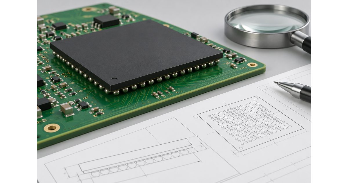
Table of Conent
Table of Conent
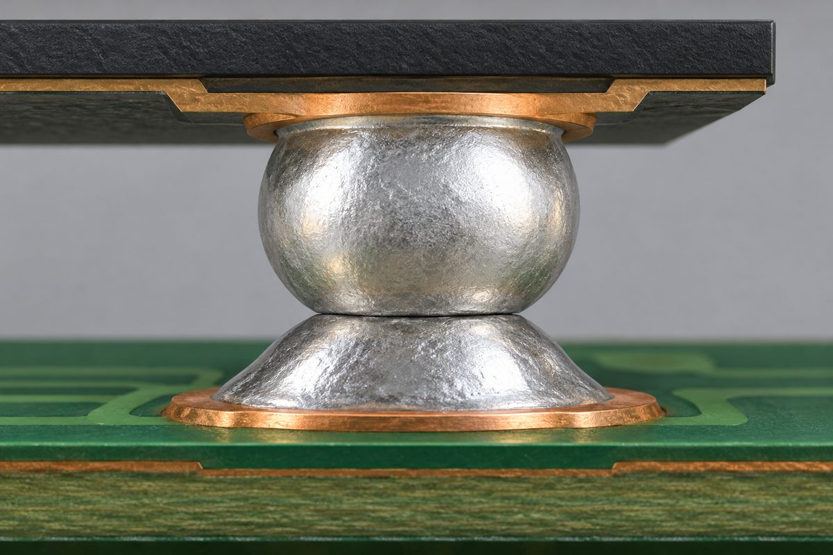
BGA head-in-pillow is an incompletely joined interface between a package solder sphere and the solder deposited on the PCB. The two bodies can reflow without merging into the intended joint. Because the connection lies beneath the package, the investigation needs more than a normal-looking component or a single passing test.
Start by locating the suspect connection and confirming what the available evidence actually shows. Then review the process conditions associated with that site. This guide provides a practical investigation and release framework, not a universal reflow recipe or an acceptance standard.
Define the suspected failure precisely
An IPC-hosted technical paper on head-in-pillow describes incomplete coalescence and the roles of wetting and package or board deformation. Those mechanisms explain why final proximity between two solder bodies does not necessarily establish a sound bond.
Do not use head-in-pillow as a label for every BGA open. Inadequate solder, a different non-wet interface, damage elsewhere in the interconnect, or another assembly issue can produce an electrical symptom. State which interface is suspected and what evidence supports that classification.
Separate observation from explanation in the report. “A discontinuity was observed at this interface” is different from “the package warped during reflow.” The second statement needs supporting evidence about the actual process, not only the shape of one final joint.
Preserve the board and establish location traceability
Record the board identifier, revision, assembly side, package reference, lot, panel position, and test or inspection stage. Preserve the original failure condition before rework. A repaired package may no longer retain the evidence needed to understand how its first assembly failed.
Map the suspected ball location consistently between package coordinates, board orientation, electrical net, and inspection images. Define the viewing direction and indexing convention. A mirrored or rotated interpretation can send a destructive examination to the wrong joint.
Keep unaffected comparison sites and boards available. Record any manipulation, cleaning, heating, or mechanical loading that occurred before analysis. These actions can change a marginal connection or introduce damage, making the original symptom harder to interpret. Before transferring samples to a laboratory, agree on the coordinate map, examination sequence, retained controls, and reporting format. Confirm which specimens will remain intact if the first analysis does not resolve the question.
Match the inspection method to the question
Ask what the method can resolve at the suspected interface. A top-down image, an angled view, and a three-dimensional reconstruction do not provide identical information. Keep the acquisition conditions and image interpretation available rather than attaching an unexplained pass/fail screenshot.
Texas Instruments’ FCBGA package reference guide discusses automatic X-ray inspection and confirmation of suspected findings, including accessible perimeter inspection. Its device-specific guidance is useful context, not a guarantee that one method proves every joint on every package.
When the evidence remains ambiguous, have the responsible analysis team select a complementary examination. Any sectioning, removal, or other destructive work should have a documented objective, location, and interpretation plan. Preserve enough context to distinguish a pre-existing interface problem from preparation damage.
A hidden location is not automatically uninspectable, and a visible image is not automatically decisive. Report the method’s actual result and limitations. If the available equipment cannot resolve the suspected interface, record that uncertainty instead of marking the mechanism confirmed.
Need help defining an investigation package? submit the assembly files, package identity, failure location map, inspection images, test symptoms, quantities, and analysis requirements for engineering and quotation review. Include the evidence that still needs confirmation.
Check what electrical testing did and did not cover
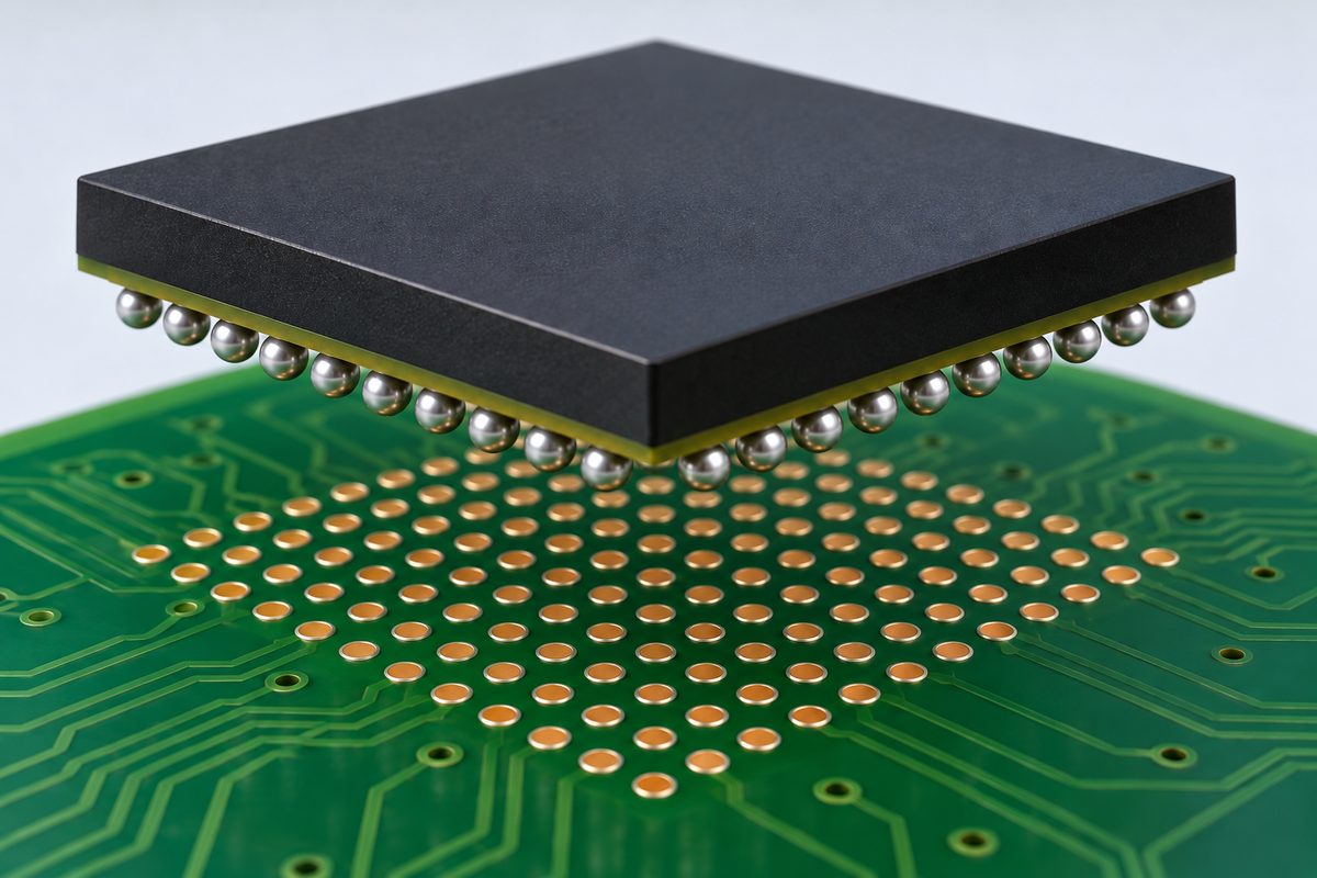
Reconcile the failed symptom with the implemented test sequence. Identify the exercised nets, operating state, firmware, limits, and any repeated-test behavior. A pass on a different function does not establish the condition of the suspected ball interface.
The test access and coverage guide explains why physical access and actual detection coverage are different. Apply that distinction to the BGA: access to a nearby node does not necessarily identify which connection or device caused a symptom.
If the failure is intermittent, preserve the conditions under which it appears. Record temperature, loading, handling, and test sequence where relevant, without deliberately stressing the board outside an approved procedure. An uncontrolled demonstration can alter the connection and obscure the original condition.
Use the electrical evidence to guide the investigation rather than to replace physical confirmation. Keep a clear statement of unresolved possibilities. A test result can be strong evidence of a problem while still being insufficient to name its exact manufacturing mechanism.
Reconstruct printing and placement at the affected package
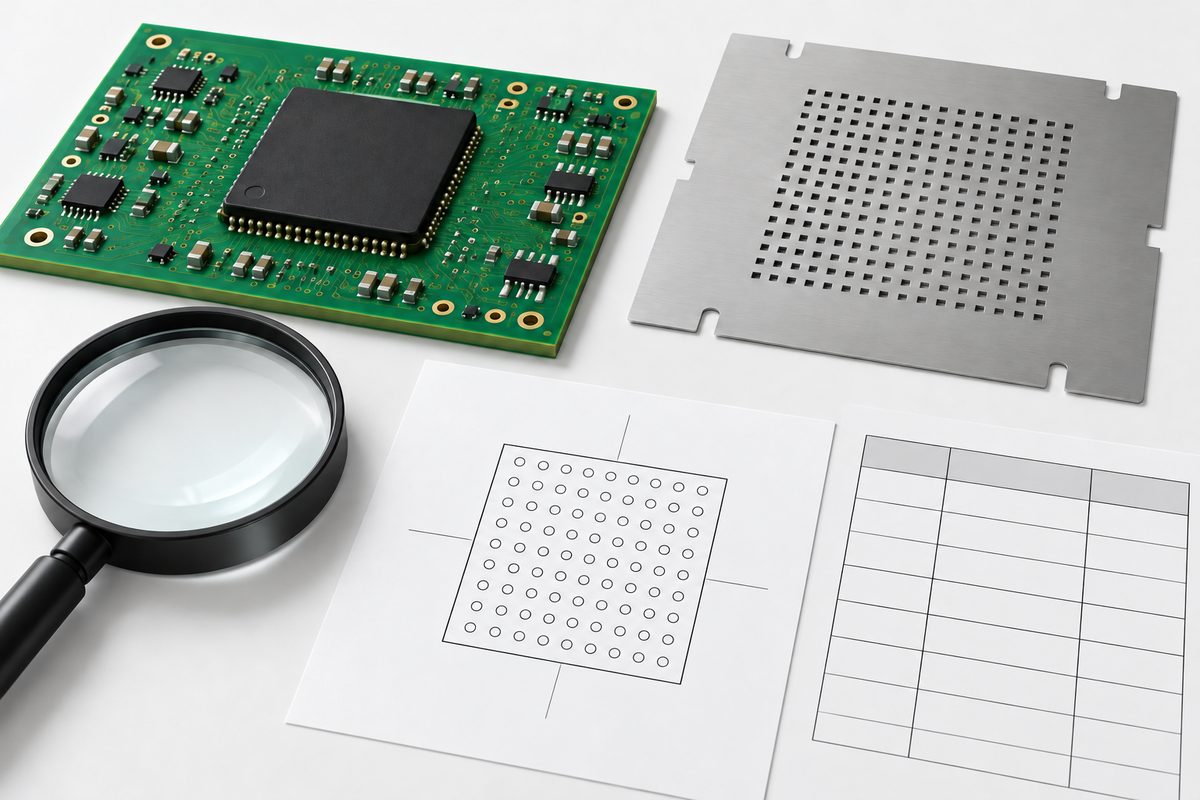
Review the actual stencil, layout, printing program, and inspection model used for the lot. Compare the package’s deposit pattern with unaffected instances. Check positional alignment, deposited geometry, and relevant process changes before assuming that the selected paste alone is responsible.
Use solder-paste inspection evidence at the individual pad and package level. Confirm that the recorded locations, nominal geometry, and measurement settings match the released stencil. An averaged package result can conceal variation that deserves a closer review.
Examine the relevant placement setup, package identity, and pre-reflow condition. Preserve records of orientation, seating, and any setup changes. Do not infer actual contact throughout a BGA array solely from the programmed position or a visually level package top.
If a proposed aperture or placement correction changes the process, state what evidence it should improve. Check all intended joints and relevant component families during the trial. Increasing deposited material indiscriminately can introduce new problems instead of isolating the original one.
Review material history without assigning blame
Collect the exact component and board lots, approved finishes, paste product and lot, and storage and handling records. Identify substitutions or repackaging. Missing history should remain a documented gap rather than being interpreted as proof of either good or bad material condition.
Ask the component supplier for relevant package handling and assembly information. Use current device-specific recommendations for any drying or thermal treatment. Extra baking or heating should not be introduced as an undocumented cure for an unknown interface condition.
Preserve suspect and comparison samples when seeking supplier analysis. Give the supplier the observed condition, chronology, and test evidence without declaring an unproven cause. A repeatable finding associated with one lot is a useful lead, but it still requires a controlled comparison.
Evaluate the thermal and deformation hypothesis
Review a measured process profile from a representative assembly, with the relevant load and conveyor conditions. Map the measurement sites to the package and surrounding board. Oven setpoints alone do not describe the thermal history at every joint.
If deformation is suspected, ask what evidence is available during the relevant thermal cycle. A room-temperature flatness result does not directly establish the shape during soldering. Document the measurement conditions and how closely they represent the production configuration.
Assess a proposed thermal change against paste, package, board, and other component constraints. Do not make the profile hotter or longer simply because a connection did not merge. The trial needs to address the suspected mechanism while preserving the complete assembly requirements.
For a controlled trial, send the PCB and stencil revisions, approved BOM, material lots, measured profile, package information, quantities, and trial objective for a manufacturing and quotation review. State which measurements and limitations the trial must preserve.
Create a decision record for the next build
Define the baseline, proposed explanation, changed factor, and verification plan before running the trial. Keep inspection settings and reviewed locations comparable. If several factors change together, state that the result cannot isolate their individual contributions.
A hypothetical example is a repeated suspect interface near one package corner while printing records show no equivalent corner-specific difference. That pattern can justify examining thermal behavior and geometry, but it does not prove deformation. A verification trial should distinguish that explanation from remaining alternatives.
Discuss the controlled release with the SMT assembly service team. Confirm project-specific inspection, testing, analysis, and acceptance deliverables. A general service page does not establish that a particular X-ray method or destructive analysis is included.
Keep lot containment separate from permanent corrective action. Reworking an affected package may resolve that board without validating the next production run. Preserve approved dispositions, actual trial observations, and the design or process revisions that changed.
Pre-release checklist
- Locate the suspect interface and maintain ball-to-net traceability.
- Preserve original boards and document prior manipulation.
- Record what inspection and electrical tests actually establish.
- Compare printing, placement, material history, and measured thermal evidence.
- Test a scoped explanation without exceeding applicable requirements.
- Separate lot disposition from the approved preventive release.
BGA head-in-pillow investigations work best when each conclusion has supporting evidence. Confirm the interface, preserve uncertainty where it remains, and verify the correction before relying on it for repeat production.
Preparing a repeat build? submit fabrication files, BOM, stencil and placement data, investigation records, verification requirements, and quantities for engineering review and quotation. Include unresolved findings and accepted corrective changes.
Latest Blog
Contact Info
Phone: +86-755-82882936
Email: [email protected]
WhatsApp: +86-13570802455
Wechat: +86-13570802455
Address: 2nd floor,D Bldg.,Electric Link Technology Bldg.,Gongming,Guangming New Dist.,518106 Shenzhen, China