
PCB Assembly Variants: Control DNP Parts and Release Files
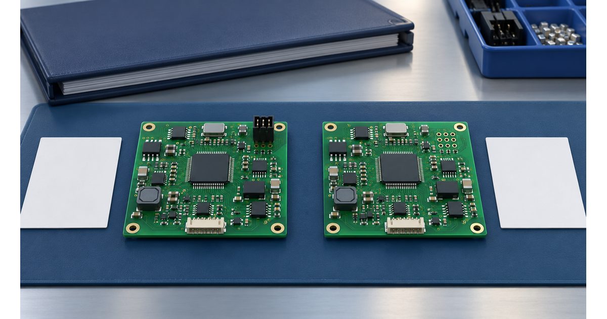
Table of Conent
Table of Conent
A PCB assembly variant is a defined population of a board design: certain components are fitted, omitted, or changed to create a particular product configuration. The manufacturing risk is not simply forgetting one resistor. It is sending a BOM for one configuration, placement data for another, and a test instruction that cannot distinguish the two.
Good variant control gives each build a clear identity and a consistent release package. This guide explains how to manage do-not-populate (DNP) parts, quantities, drawings, placement files, stencil decisions, and configuration-specific acceptance. It focuses on assembly configurations sharing a PCB design, not on treating different copper layouts as interchangeable.
Separate the PCB revision from the assembly configuration
The bare-board revision identifies the fabricated design. The assembly part number and revision identify the populated product. A variant identifier distinguishes configurations within an approved design family. These identities may be related, but none should be inferred from a sales nickname such as “basic” or “premium.”
For example, two assemblies might use the same bare board while only one includes an optional interface connector. The configuration without that connector needs an intentional omission instruction, not a purchasing shortage note. If the connector requires different routing, drill holes, or board geometry, evaluate a separate PCB revision rather than assuming an assembly variant solves the difference.
A release cover sheet should identify the PCB revision, assembly part number, assembly revision, variant, order quantity, and approved document set. Define which document controls each decision and how conflicts are resolved. “Use the latest files” is inadequate because different files can be updated independently.
Define DNP as a controlled population state
DNP means a component is intentionally not installed for the specified build. It is different from an unavailable part, an unapproved substitute, or a component installed later by another operation. Use one defined term consistently across the release package, even if the design software calls the state “not fitted.”
Give every relevant reference designator an explicit population state. A master configuration matrix can retain all designators, while the build-specific procurement BOM lists the parts actually required. If DNP rows remain in that BOM for visibility, mark them unmistakably and define how quantities are interpreted. A blank manufacturer part number is not a reliable omission instruction.
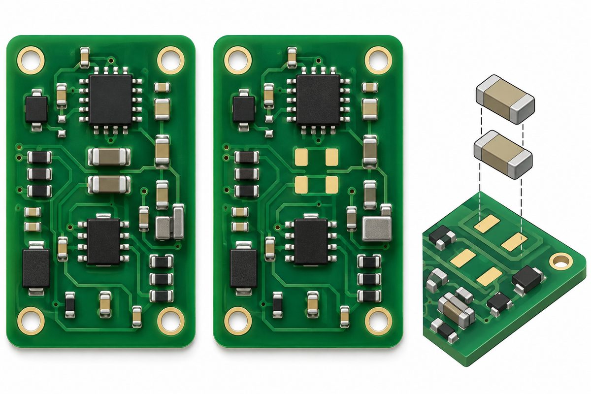
Keep “not installed” separate from “excluded from this file.” A through-hole connector installed manually may be absent from an SMT placement export yet still belong in the assembly BOM. Conversely, a footprint retained for an unused option can appear in the CAD layout without authorizing installation.
Build a configuration matrix before exporting files
A compact matrix makes differences reviewable without forcing the assembler to compare entire BOMs. Include the reference designator, configuration-specific population state, exact part identity where fitted, and any related process or verification note. Grouping common components is useful, but list configuration-sensitive items explicitly.
| Illustrative item | Configuration A | Configuration B | Release check |
|---|---|---|---|
| Optional connector J2 | Fitted | DNP | BOM, drawing, and operation instructions agree |
| Configuration resistor R18 | Approved value A | Approved value B | Exact part and configuration detection verified |
| Common controller U1 | Fitted | Fitted | Common approved identity remains unchanged |
| Programming step | Image A | Image B | Firmware identity recorded against the assembly |
This example is a documentation pattern, not a recommended circuit. Changing a resistor value or omitting a connector requires engineering evaluation of the actual design. An optional circuit can affect power states, leakage, default logic levels, EMC behavior, or test access even when its footprints remain unchanged.
Before requesting pricing, send the configuration matrix, assembly quantities by variant, and the shared PCB revision for a quote review. State whether components are supplied, sourced, or split between responsibilities; do not assume all variants have the same material availability.
Cross-check the BOM, drawing, and placement export
Generate outputs from the approved source revision with the intended configuration selected. Then inspect the exported files themselves. A correct CAD view does not prove that a saved spreadsheet, PDF, or position file contains the same configuration.
Compare reference-designator sets across the documents. Every fitted SMT component should have an explained route into assembly programming. Every DNP position should be consistently identified or excluded according to the agreed import method. Any fitted part missing from placement data needs a defined manual or separate operation, not an unexplained exception.
Check quantity per assembly against the actual reference-designator count. Keep build quantity and procurement allowance in separate fields so overage cannot be confused with fitted quantity. When one BOM row groups many references, ensure none of the grouped references has a different variant state or part identity.
The coordinate convention remains important even when population is the main issue. Use the pick-and-place file checks to review origin, units, side, rotation, and reference matching. Configuration control cannot compensate for an incorrect bottom-side transformation.
KiCad’s PCB Editor documentation distinguishes footprint exclusion from position files and optional exclusion of DNP footprints. That behavior illustrates why the manufacturing import convention must be agreed explicitly instead of assumed from an attribute name.
Review stencil and process implications separately
An omitted component does not automatically answer whether paste should be printed on its lands. Decide with the assembly process owner whether the variant uses a shared stencil, a variant-specific paste pattern, or another controlled method. Consider the unused deposit, nearby components, inspection interpretation, and future operations.
For software-specific output behavior, Altium’s variant documentation describes an option that removes paste-mask openings for not-fitted components. Do not assume merely selecting a variant changes every fabrication output. Inspect the exported paste layers and match the approved stencil identifier to the build.
Also review handling and support. Removing a large component may change the assembly’s mechanical support needs or visual inspection expectations. Different fitted components can require changed feeders, placement settings, thermal review, or manual operations. Record applicable decisions without prescribing universal machine parameters.
For the production handoff, review the relevant SMT assembly requirements alongside the configuration package. Identify unresolved process questions before release rather than relying on the assembler to interpret ambiguous omissions.
Keep variant changes separate from substitute approval
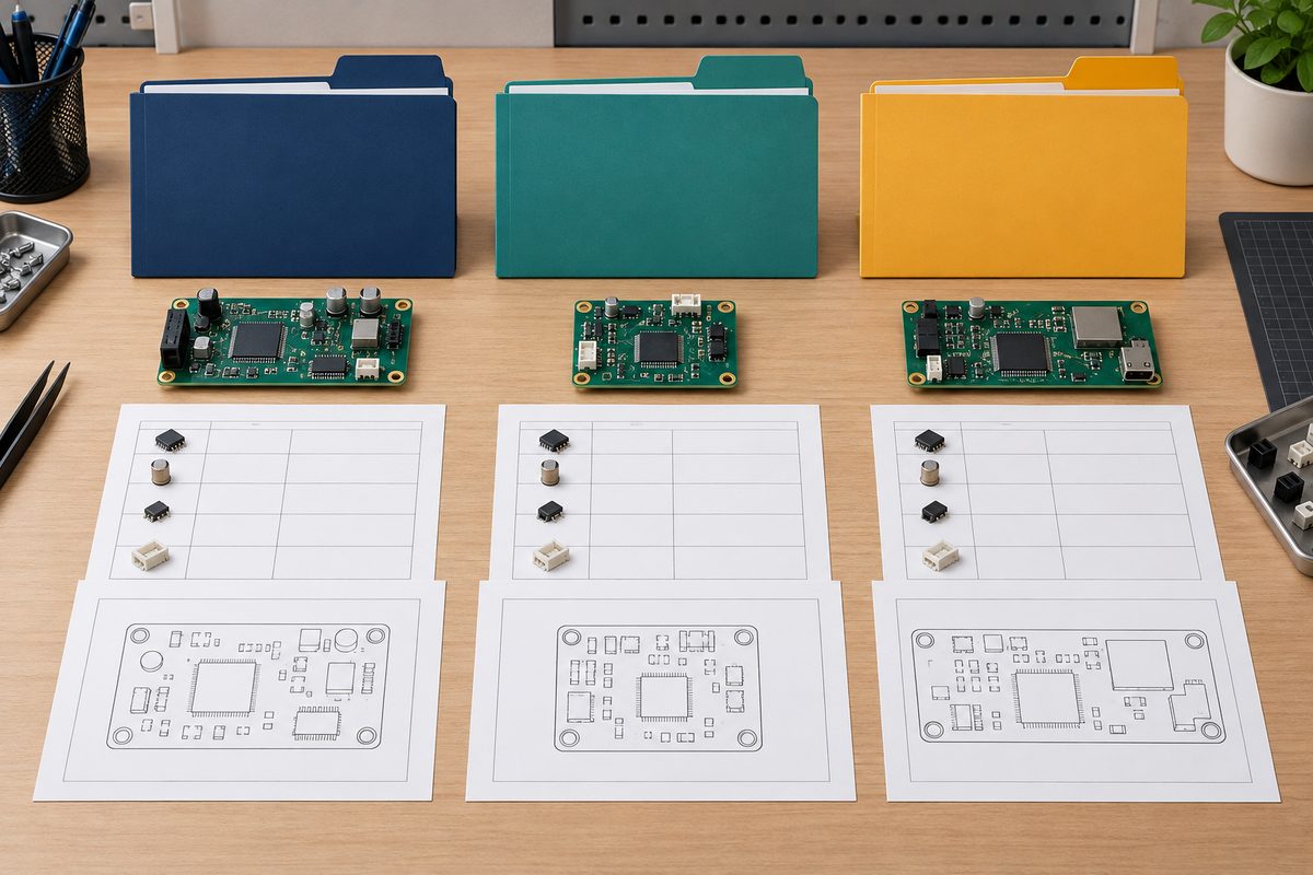
A product variant intentionally changes the configuration. A substitute supplies an approved alternative within a defined configuration. Mixing the two creates uncertainty over whether a changed component is mandatory, optional, or a shortage workaround.
Use the BOM alternate approval workflow for substitute evaluation. State which configurations, references, revisions, and orders the approval covers. An alternative accepted for one configuration is not automatically approved for every product sharing the footprint.
A revision change needs an effective scope as well: the affected orders, work in progress, stocked assemblies, and any permitted rework. Preserve the previous released package. Replace neither individual BOM cells nor shop-floor notes without controlling the complete affected document set.
If the configurations or revision boundaries are unclear, submit the variant BOMs, drawings, and open release questions with your quote request. Include the desired build split so the discussion addresses the actual order rather than a generic master BOM.
Verify the configuration, not just solder quality
A board can have acceptable-looking joints and still be the wrong product. First-article verification should check fitted identities, intentional absences, configuration-specific operations, and the test procedure selected for that assembly. Inspection instructions should distinguish an expected empty footprint from a missing-component defect.
Where test limits or firmware differ, bind their identifiers to the assembly configuration. Record the programming image, relevant checksum or other approved identity, test procedure revision, and result against the unit or defined production record. Use the product’s engineering requirements to determine the needed checks; not every option is detectable by a general power-on test.
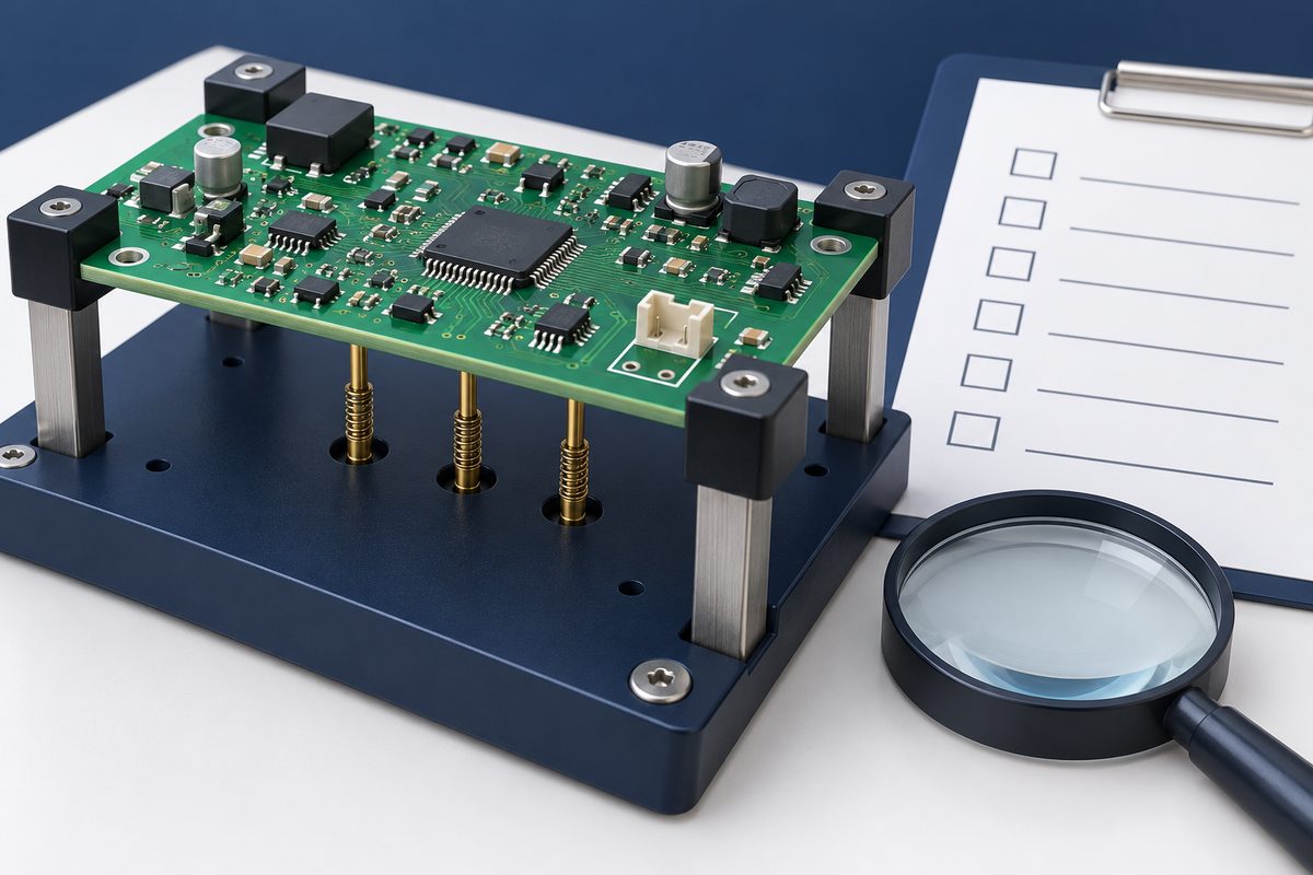
For an optional interface, test both the intended enabled behavior and the relevant disabled-state requirements. An absent connector alone does not prove the interface circuitry is disabled. Maintain separation of finished configurations through identification, packaging records, and shipment documentation.
Pre-release checklist
For a mixed-variant order, define the build split explicitly rather than giving only a total board count. Separate kits or controlled material issue records should identify the destination configuration. At a changeover, reconcile remaining materials and verify the newly selected program, drawing, and test instruction before continuing. If a configuration mismatch is discovered, contain the affected units and establish their actual population before deciding whether rework is permissible. An undocumented conversion between variants is not a substitute for an approved rework instruction and repeat verification.
- Confirm the shared PCB revision and each assembly identity, revision, and variant.
- Resolve every fitted, DNP, later-installed, and substituted component state.
- Match BOM quantities and exact identities to the reference-designator matrix.
- Compare assembly drawings and placement exports against the same population.
- Approve paste output, stencil identity, and configuration-specific operations.
- Identify firmware, inspection instructions, tests, and acceptance requirements.
- Define change effectivity, document ownership, and conflict-resolution authority.
- Verify finished-unit identification and quantities for each configuration.
The release is ready when an assembler can build the requested configuration without deciding which conflicting file to trust. Request an assembly quote with the controlled release package and quantities for each variant, including any unresolved sourcing, stencil, programming, or verification questions.
Latest Blog
Contact Info
Phone: +86-755-82882936
Email: [email protected]
WhatsApp: +86-13570802455
Wechat: +86-13570802455
Address: 2nd floor,D Bldg.,Electric Link Technology Bldg.,Gongming,Guangming New Dist.,518106 Shenzhen, China