
How to Evaluate a 4-Layer PCB Manufacturer Before You Send Gerbers
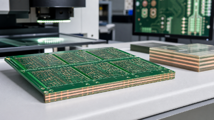
Table of Conent
Table of Conent
The right 4-layer PCB manufacturer should confirm your stackup, review impedance-sensitive routing, check manufacturability, and support assembly planning before production starts. A 4-layer board is common, but supplier quality still affects EMI, soldering, lead time, and field reliability.
If you are still deciding whether your design needs 4 layers, start with our 4-layer PCB design guide. This article focuses on supplier selection.
Start With Stackup Control
A 4-layer PCB depends on dielectric spacing. If the supplier changes prepreg or core thickness without telling you, impedance and return-path behavior can shift.
Ask for a stackup confirmation that includes:
- Finished board thickness.
- Copper weight on each layer.
- Core and prepreg thickness.
- Material grade and Tg.
- Solder mask and surface finish.
- Impedance coupon requirement, if controlled impedance is needed.
| Supplier Response | What It Usually Means |
|---|---|
| “We use our standard 4-layer stackup” | Fine for simple designs, risky for impedance-critical boards |
| “Send target impedance and trace geometry” | Better engineering engagement |
| “We will confirm stackup before fabrication” | Best for controlled or production designs |
For broader multilayer context, see multilayer PCB design to production.
Why “Standard Stackup” Is Not Always Enough
A standard 4-layer stackup is useful for cost and lead time. It becomes a problem when the design was routed around a different dielectric thickness or copper weight. A few mils of spacing change can affect controlled impedance, especially on USB, Ethernet, RF, and fast clock lines.
The manufacturer does not need to redesign your board. They do need to confirm whether the geometry you used matches their process. If not, you should adjust the trace width, spacing, or layer assignment before production.
| If Your Board Has | Ask the Manufacturer For |
|---|---|
| USB, Ethernet, LVDS, RF | Impedance review against their stackup |
| Switching regulators | Plane and current-loop review |
| Fine-pitch parts | Solder mask and surface finish review |
| Tight enclosure fit | Finished thickness tolerance |
| Production volume | Panelization and test plan |
Check DFM Feedback Quality
A strong manufacturer does not only check whether the Gerbers open. They check whether the board can be built with stable yield.
Good DFM feedback should identify:
- 1. Trace and spacing violations.
- 2. Drill-to-copper clearance risk.
- 3. Solder mask slivers.
- 4. Copper imbalance.
- 5. Board outline or slot ambiguity.
- 6. Panelization concerns.
- 7. Assembly risks from component placement.
A weak review says “files are okay” without details. That may be acceptable for hobby prototypes, but not for production hardware.
What a Useful DFM Comment Looks Like
Generic DFM feedback says, “Minimum annular ring is small.” Useful DFM feedback says, “J3 pin 4 has a 0.18 mm annular ring after drill tolerance. Increase pad diameter from 1.1 mm to 1.3 mm or reduce finished hole size.”
That difference matters. Specific comments help engineers make a decision quickly. Vague comments create another round of emails.
Ask your 4-layer PCB manufacturer whether DFM feedback includes screenshots, layer references, and recommended fixes. If the answer is yes, you are more likely to catch problems before copper is etched.
Compare Quotes by Manufacturing Scope
Two 4-layer PCB manufacturer quotes can look close on unit price but differ in what they include. Ask what is covered before choosing.
| Quote Item | Must Clarify | Why It Matters |
|---|---|---|
| Electrical test | Included or extra | Catches opens and shorts before shipment |
| Impedance | Simulated only or coupon-tested | Affects high-speed confidence |
| Surface finish | Exact finish and shelf life | Impacts solderability and storage |
| Lead time | Fabrication only or PCBA total | Avoids schedule surprises |
| Packaging | Vacuum pack, desiccant, humidity card | Protects solderability |
Our guide on PCB price factors explains why board area is only part of the cost.
Materials and Surface Finish Questions
Most 4-layer boards use FR-4, but FR-4 is not one single material. Tg, dielectric performance, copper foil, and laminate availability can vary. For ordinary embedded products, standard FR-4 may be enough. For higher temperature, lead-free assembly, automotive, RF, or high-reliability applications, material selection deserves more attention.
Ask these questions:
- What base material will be used?
- Is high-Tg material available?
- Is the material suitable for lead-free assembly?
- What surface finishes are available?
- Can the finish support the component pitch?
- Will substitutions be approved before production?
| Requirement | Sensible Material or Finish Direction |
|---|---|
| General prototypes | Standard FR-4, HASL or lead-free HASL |
| Fine-pitch SMT | ENIG or another flat finish |
| Higher temperature | High-Tg FR-4 |
| Longer storage | ENIG or controlled packaging |
| Cost-sensitive large pads | HASL or OSP where suitable |
The manufacturer should explain the trade-off rather than pushing the most expensive option.
Assembly Capability Can Save a Project
Many 4-layer PCBs are dense enough that assembly planning matters. If your supplier can also handle PCBA, they can review the board, BOM, and placement data as one package.
This matters when the design includes:
- Fine-pitch QFP or QFN packages.
- Dense connectors.
- BGAs or bottom-terminated parts.
- Mixed SMT and through-hole assembly.
- Functional test requirements.
For ordering details, use our guide on how to order PCB assembly service.
Supplier Scenario: The Board That Was Easy to Fabricate but Hard to Assemble
A hardware team designs a 4-layer control board with a compact QFN regulator, a board-to-wire connector, and test pads on the bottom side. The bare board supplier approves the Gerbers because the line width, spacing, and drill sizes are all within capability.
During assembly, the problems appear. The QFN thermal pad needs stencil modification. The connector creates local shadowing during inspection. The bottom-side test pads are too close to tall components for the fixture probe angle.
None of these are bare-board failures. They are manufacturing workflow failures. A 4-layer PCB manufacturer with assembly experience would review the full PCBA package and flag them earlier.
Lead Time and Prototype-to-Production Planning
Fast prototypes are useful, but a prototype process should not hide production issues. If the first order is for 5 boards and the second order may be 2,000 boards, ask whether the same stackup, finish, and inspection method can scale.
| Stage | What to Confirm |
|---|---|
| First prototype | Fast DFM, standard stackup, basic test |
| Engineering validation | Impedance and assembly feedback |
| Pilot build | Panelization, sourcing, inspection method |
| Production | Repeatable stackup, traceability, test records |
The best time to discuss production is before the prototype is ordered. Small layout changes after EVT can save expensive changes after pilot production.
Inspection and Testing Questions
Ask the manufacturer how they inspect both bare boards and assembled boards. For bare boards, electrical testing is the baseline. For assembly, AOI is common for visible solder joints, while X-ray may be needed for BGAs or QFNs.
| Inspection Step | Best Used For | Ask the Supplier |
|---|---|---|
| Electrical test | Bare-board opens and shorts | Is every production board tested? |
| AOI | SMT placement and visible joints | What defect types are checked? |
| X-ray | Hidden solder joints | Is it available for BGA/QFN builds? |
| Functional test | Product-level behavior | Can you build a fixture or follow our test plan? |
Learn more about automated optical inspection in PCB manufacturing.
FAQ: Working With a 4-Layer PCB Manufacturer
Should I ask for controlled impedance on every 4-layer PCB?
No. Ask for controlled impedance when the design has nets that require it. Examples include USB, Ethernet, RF, LVDS, fast clocks, and some memory interfaces.
Can the manufacturer change the stackup after I send files?
They can propose changes, but they should not silently change a stackup that affects impedance, thickness, or mechanical fit. Production should start only after stackup approval.
What if I only have Gerber files?
Gerbers can be enough for bare-board fabrication, but assembly requires BOM and placement files. For production, a fabrication drawing and test requirements are also helpful.
Is a local manufacturer always better?
Not necessarily. The better choice is the manufacturer that can meet your technical requirements, communicate clearly, provide DFM feedback, and support your lead time and quality needs.
What is the most important supplier capability?
For 4-layer boards, stackup confirmation and meaningful DFM feedback are the first filters. If assembly is included, inspection and component sourcing become just as important.
Procurement Notes for 4-Layer PCB Buyers
Procurement teams often compare 4-layer PCB manufacturers by price, lead time, and shipping terms. Those are important, but they do not tell the whole story. A supplier with stronger engineering review can prevent a respin that costs far more than the bare-board savings.
When comparing suppliers, ask for a quote breakdown. The breakdown should show bare PCB cost, tooling, surface finish, impedance testing if required, assembly cost, component sourcing, inspection, packaging, and freight. If one quote is much lower, identify the missing line item before choosing it.
Also confirm communication flow. For production orders, you should know who reviews DFM questions, who approves substitutions, who handles test failures, and who signs off before shipment. A manufacturer with one clear project contact is usually easier to manage than a chain of disconnected teams.
For repeat orders, ask whether the same stackup and material will be held. A 4-layer PCB that passes validation should not quietly change construction in the second batch. Even small material or dielectric changes can matter for impedance-sensitive products.
Final Decision Matrix
Use this simple matrix when choosing between two qualified suppliers.
| Decision Factor | Weight for Prototype | Weight for Production |
|---|---|---|
| Price | Medium | Medium |
| Lead time | High | Medium |
| Stackup support | Medium | High |
| DFM detail | Medium | High |
| Assembly capability | Medium | High |
| Test coverage | Low to medium | High |
| Communication | High | High |
| Repeatability | Medium | High |
For a one-off prototype, speed may matter most. For production, repeatability and engineering support should carry more weight.
Red Flags When Selecting a 4-Layer PCB Manufacturer
Be cautious if a supplier cannot answer basic stackup questions, refuses to review drill-to-copper clearance, or treats impedance as a checkbox. Also watch for unclear communication about lead time, substitution of materials, and assembly limitations.
A common scenario: a procurement team selects the lowest 4-layer quote for a connected sensor board. The boards arrive on time, but the RF section performs inconsistently because the stackup changed from the engineer’s model. The board is not “bad” in a visual sense. It is just not the board that was designed.
Final Selection Checklist
Choose a 4-layer PCB manufacturer that can:
- 1. Confirm stackup before release.
- 2. Review manufacturability, not just file format.
- 3. Support impedance requirements when needed.
- 4. Provide electrical test and inspection.
- 5. Handle assembly and sourcing if you need PCBA.
- 6. Communicate design risks early.
AssyPCB supports 4-layer fabrication, DFM feedback, component sourcing, assembly, AOI, X-ray, and functional test. Send your design package and we will help you move from stackup review to production with fewer surprises.
Latest Blog

Contact Info
Phone: +86-755-82882936
Email: [email protected]
WhatsApp: +86-13570802455
Wechat: +86-13570802455
Address: 2nd floor,D Bldg.,Electric Link Technology Bldg.,Gongming,Guangming New Dist.,518106 Shenzhen, China