
Airborne Weather Radar PCB Failures: Diagnose Intermittent Field Returns
Table of Conent
Table of Conent
An airborne weather radar processor PCB can pass a room-temperature bench check and still drop frames, reset, or lose its link in service. Start with the symptom as reported. Preserve the returned printed circuit board assembly (PCBA), its software or logic image, and its mating conditions. Then recreate the symptom on an approved bench setup while recording power at the board, reset, input traffic, and output status against a shared time reference.
Compare the returned assembly with a known-good unit of the same approved configuration. If the fault follows one board across verified test paths, narrow the analysis to the affected circuit. If it follows one cable or fixture, investigate that path before authorizing board work. When the symptom cannot be reproduced, document the exposure, observable signals, and gaps. That record determines whether to improve the diagnostic setup, localize a physical fault, or transfer a confirmed finding into production testing.
Preserve the returned assembly and its configuration
Capture the as-returned baseline before reseating connectors, reloading firmware, or removing the board. Ask for the equipment serial number, assembly and board revision, firmware or FPGA image identifiers, failure code, operating mode, time since power-on, and any observations about temperature, power disturbances, or vibration. Retain the original log and record the clock it used. Log times can be consistent within one instrument and offset from every other device.
Describe what the processor actually does between its inputs and outputs. One unit may receive digitized radar data and pass processed frames to a display. Another may include converters or additional interface electronics. A display report of missing returns could begin at the source, at a connector, inside the processing chain, or at the receiving end. Start the bench plan with a known stimulus, a measurable expected output, and the actual points where each interface can be observed. The weather radar processor manufacturing handover describes the baseline documents that can supply those points.
Record the fixture, harness, and power-source revisions alongside the returned configuration. The DLA intermittent-fault diagnostic equipment specification addresses intermittent faults in conductive paths such as chassis backplanes and wiring. It provides context for testing those paths separately. Functional processing and interface checks still need stimulus and observation points defined for the equipment.
Record which signal changes first
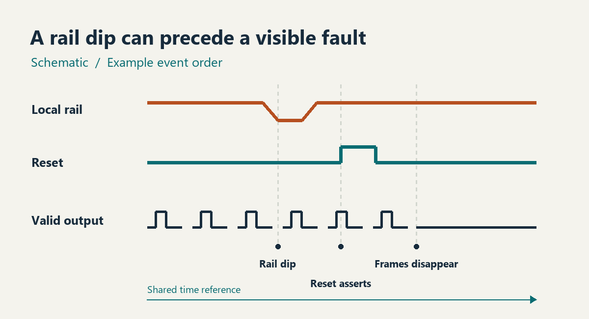
Capture events before and after the symptom trigger so a downstream error can be traced to an earlier change. Where the design permits, monitor voltage at the board input and a relevant local rail, reset or power-good, and a status signal tied to valid data. Log input stimulus and interface errors. An external timing marker recorded on both instruments can align a scope capture with a traffic log. Record the sample interval, capture bandwidth, timing uncertainty, and the trigger thresholds used for that run.
Choose a trigger that can catch the suspected event. The Tektronix oscilloscope primer explains how pretrigger acquisition and pulse-qualified triggering reveal transients that a periodic status poll can miss. Trigger on a brief excursion if a rail is suspect, or on a missing heartbeat if the available event is digital. When a visible error starts the capture, allow enough pretrigger history to cover plausible precursors. Check that the probes and fixture do not alter the behavior you are investigating.
| Recorded sequence | Working hypothesis | Next measurement |
|---|---|---|
| Board input drops before the local rail and reset | Supply, protection, connector, or harness upstream of the regulator | Compare the supply output with voltage at the board input during the same event. |
| Board input holds while a local rail drops before reset | Local regulation, load transient, or distribution path | Compare regulator output and load-side voltage with the current or enable state. |
| Link errors start while observed rails and reset hold | Interface, cable, timing, or termination | Check the same traffic at each end with an independently verified path. |
| Input remains valid and the expected output disappears | Processing, clock, memory, or embedded logic | Inspect approved counters or status points using the same stimulus and image. |
Two changes that fall within the timing uncertainty should be recorded as unresolved in order. For a fixture that will need to capture those changes in production, share the interface and event-capture requirements with the approved access points, stimulus, and symptoms. The review can identify probe access and fixture requirements to price into the build.
Separate the returned board from the test path
Change one element per run and compare the returned unit against a configuration-matched reference. Test both assemblies on the same verified path before repeating on an independent, documented path if one is available. Hold power settings, stimulus, environmental conditions, software, and observation time constant. If warming changes the result, record the temperatures at the relevant measurement locations and the time at load. Keep all exposures within the program-approved test plan.
| Repeatable outcome | Next decision |
|---|---|
| Only the returned assembly fails across both paths | Investigate the implicated board circuit and preserve a repeatable electrical signature. |
| Both assemblies fail through the same path | Verify the path, stimulus, and instruments before assigning the symptom to the board. |
| Only one board and path combination fails | Investigate the mating interface, tolerance interaction, and test loading. Keep both parts identified. |
| Neither fails under the available exposure | Record “not reproduced under tested conditions,” exposure, measurement limits, and the next evidence needed. |
Use the same serial numbers and known test duration in each comparison. For sparse events, capture time matters as much as the number of runs. If a cable swap changes the mating condition, record that disturbance and which connector halves moved. An intermittent contact can disappear during handling and leave both later combinations passing. Preserve ambiguous run results as well as repeatable ones. If no independent path is available, state that limit in the analysis record.
Match physical findings to the electrical fault
Inspect the physical location implicated by an observed net or interface before choosing a destructive technique. Photograph the board and mated features as received. Record the connector cavity, pad, via, or component coordinates, plus how the suspect path was isolated. Visible inspection can document exposed joints, displaced contacts, or nearby mechanical damage. Choose X-ray views or other methods according to what feature and depth they can actually resolve. NASA Goddard PCB reliability training distinguishes pad craters in the laminate from solder fractures and trace failures in BGA failure analysis.
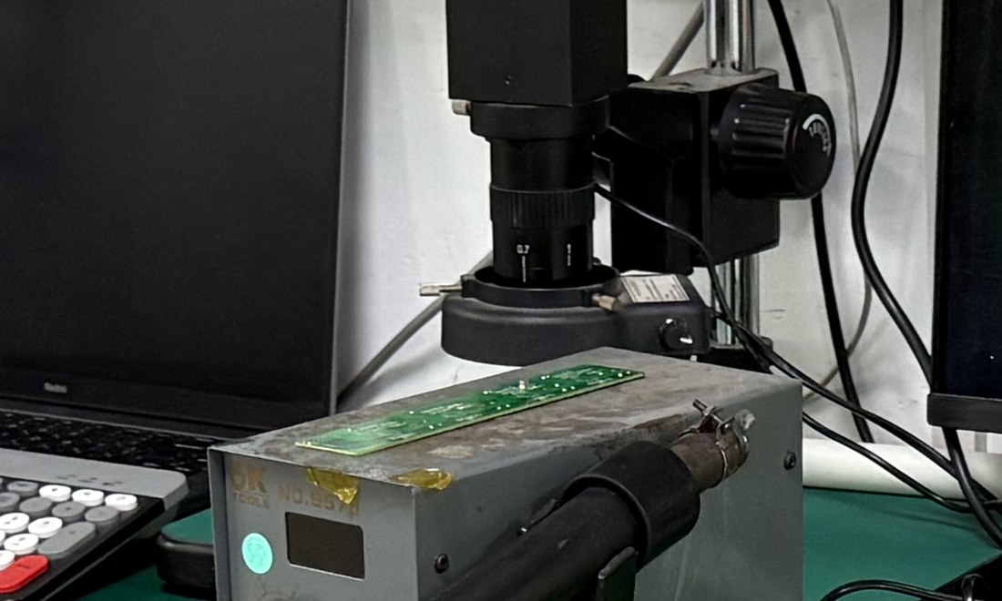
OrinewPCB’s pad-cratering video illustrates one subsurface mechanism that can escape an initial inspection. In a returned radar assembly, use the electrical evidence to decide whether that mechanism warrants targeted analysis.
With approval, consider sectioning or dye-and-pry for a localized area and preserve a comparison sample when available. Ask the analyst to map any observed damage to the implicated net and assembly serial number. A defect elsewhere on the board may still need disposition. The causal finding should account for the captured electrical sequence and the conditions that produced it.
Transfer the confirmed fault into production testing
Translate the confirmed fault into a test with explicit detection limits and a demonstrated response. Specify the stimulus, fixture and revision, timing references, observable signal, limit, exposure time, data retention, and owner of an exception. If the diagnostic used expensive instruments or test points unavailable at volume, define a production proxy and demonstrate its correlation. A shorter screen needs evidence that it detects the relevant signature under the specified conditions. The manufacturing test planning for complex PCBAs covers the broader choice of methods and access points.
Run a verified reference through the proposed screen. Where the design authority approves, challenge the fixture with a controlled, safe fault injection or an identified failing sample. Confirm that the log captures the expected failure code and enough context to distinguish a fixture problem. Record the coverage that still depends on equipment-level tests. The FAA guidance on airborne equipment environmental qualification describes applicable RTCA DO-160 environmental qualification evidence at the equipment level. Set board screening and equipment qualification requirements with the responsible program.
Specify the corrected build and its evidence
Order a corrective build against a released configuration and a test record linked to each relevant serial number. Before procurement releases the order, reconcile the failure signature, physical findings, approved corrective change, and verification plan. Ask the supplier to identify the affected lot or revision, the evidence supplied at first article, the test records delivered at shipment, and who approves further deviations. A full-turnkey PCB assembly scope can bring fabrication, component sourcing, assembly, and agreed test deliverables into the same review.
Once the change and test coverage are released, send the corrected build package and approved test matrix with the fabrication outputs, assembly drawing, BOM and approved alternates, revision and quantity, fixture ownership, and required per-unit records. The review can confirm which operations and evidence belong in the assembly quotation and identify items that need a project decision before release.
Latest Blog



Contact Info
Phone: +86-755-82882936
Email: [email protected]
WhatsApp: +86-13570802455
Wechat: +86-13570802455
Address: 2nd floor,D Bldg.,Electric Link Technology Bldg.,Gongming,Guangming New Dist.,518106 Shenzhen, China
