
Cockpit Voice Recorder PCB Design: Verify Audio Capture and Memory Readback
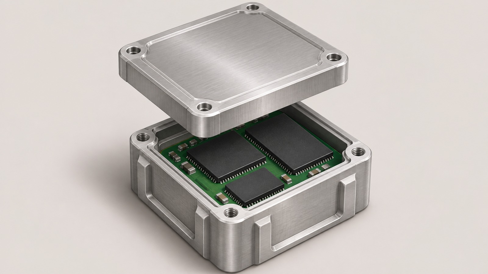
Table of Conent
Table of Conent
For a cockpit voice recorder (CVR), verify the chassis audio path and the crash-protected memory assembly at separate test points, then prove they work together in the assembled recorder. Apply a distinct synthetic signal to each input and check the channel identity, signal quality, and continuity of the decoded recording. Before the memory enclosure limits access, check the board and its interfaces, then verify readback with the approved tooling. After assembly, repeat the functional checks the product specification calls for and tie the results to the installed board and module serial numbers.
This sequence gives engineering and procurement a way to define what gets tested at each build stage. The recorder program owns channel limits, recording duration, access methods, and the qualification configuration. Production tests need those inputs before they can produce meaningful acceptance evidence.
Define what the chassis and memory module each prove
Assign one test boundary to audio capture and another to storage and readback. Verify both functions together on the assembled recorder. The exact partition depends on where a particular design places input conditioning, conversion, recording control, and memory.
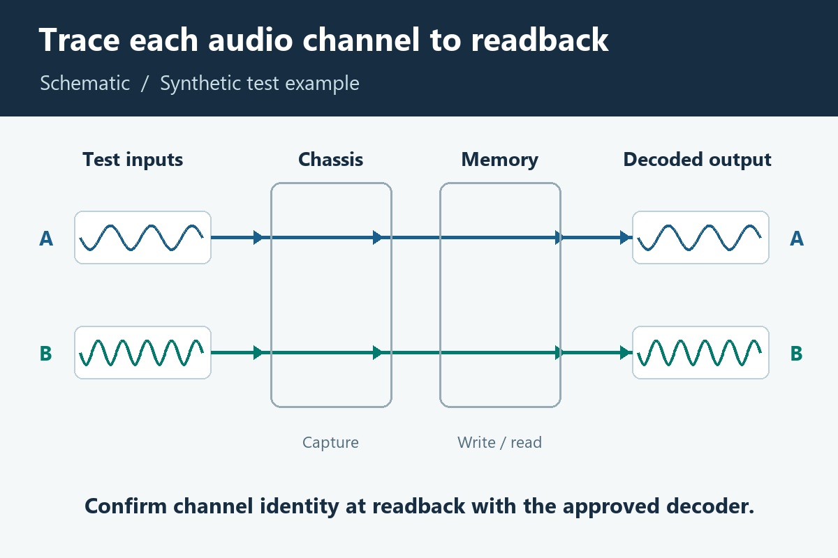
At the chassis boundary, start with a channel map that connects each input and its return to the expected decoded track. Include the cockpit area microphone (CAM) and other inputs where the approved configuration uses them. Record the source impedance, test level, gain setting, and any active filtering or mixing. Where the design provides a safe intermediate capture point, identify what it represents and which later processing steps it bypasses.
For the memory assembly, identify the board, storage device, interconnect and enclosure revisions, as well as the approved reader and record format. Define the last production stage that allows inspection and the last stage that allows the authorized module-level readback. These points can differ if a separate fixture can still access the module after closure.
The FAA guidance on airborne equipment environmental qualification treats DO-160 as environmental qualification of airborne equipment. EUROCAE’s ED-112B recorder standard addresses crash-protected recorder systems and includes audio-quality assessment in its scope. Record the configuration and the applicable standards selected by the program. Board test records document what a particular assembly did under stated conditions. The equipment qualification report documents how the representative recorder performed under the applicable test conditions.
Verify every channel from input to decoded audio
Use distinguishable stimuli and compare each decoded track with its assigned input. A shared tone applied everywhere can show that audio is present while concealing a channel swap. Set the stimulus, source impedance, inactive-channel termination, acquisition window, and thresholds in the controlled test plan.
For example, apply a distinct tone or time marker to one input at a time. End the active input segment cleanly and check the corresponding period in every decoded track. If the design allows isolation testing, terminate the inactive inputs as specified and measure any copy of the active signal on those tracks. Separate that observation from a routing or mixing function that the channel map intentionally calls for.
| Readback pattern | First check | Evidence to retain |
|---|---|---|
| The right signal appears on the wrong track | Fixture pinout, board input map, and decoder configuration | Stimulus schedule and input-to-track map for the actual revisions used |
| The expected track clips or measures low | Input level and termination, gain registers, and fitted input network | Known input level and decoded peak or gain result under the specified mode |
| A quiet track contains the active channel | Intentional mix settings, fixture coupling, and board-level crosstalk | Inactive-input termination and isolated single-channel capture |
| Intermediate capture is correct, but stored readback drops segments | Recorder processing, write path, storage interface, and approved decoder | Time-aligned intermediate capture and decoded segment with version records |
As a component-level example, Texas Instruments’ multichannel audio ADC layout guidance addresses differential routing and separation from digital signals on a specific converter. Review the recommendations for the chosen converter and measure noise and crosstalk in the board’s actual operating modes. Use the principles of manufacturing test coverage for complex PCBAs to place programming and functional checks at the appropriate stations. If fixture coverage is still being defined, share the audio interface and channel test matrix so the assembly team can review test access and the results the fixture will need to retain.
Test and document the memory board before closure
Perform the inspections that need physical access before the enclosure blocks those features. Then use the approved fixture and software to establish a known write and readback result. Define the evidence required to advance the module, including any hold point after rework.
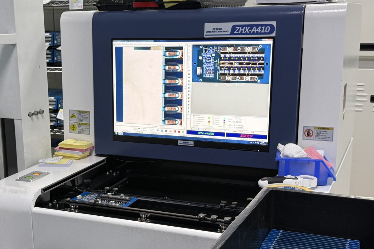
Inspect the agreed placement, workmanship and connector features. If the design calls for staking, coating, potting, or another special process, use the released drawing and record the applicable material lot, process revision and inspection result. Keep the exact board revision and memory device identity with that record. Inspection methods and coverage depend on the package and process, including whether critical joints are visible.
Use synthetic test content and a controlled reader version. Preserve the pass criteria, fixture ID, board and module serial numbers, memory and firmware revisions, and a reference to the exported test evidence. Where the format or encoding changes between test points, compare the decoded characteristics the plan specifies. A raw file hash can establish byte-for-byte identity only when both artifacts are expected to have the same bytes.
In an NTSB cockpit voice recorder factual report, investigators accessed a protected memory unit and found damage to its connection to the recorder housing. The laboratory recovered data in the expected format, and its report describes the audio on all channels as unusable. Give the factory fixture separate criteria for file readability and expected channel content so that a successful export cannot hide an empty or incorrect recording. Use authorized production access for factory acceptance and retain the program’s approved readout procedure for the delivered build.
Compare the assembled recorder with the pre-closure baseline
Verify the assembled recorder using the final connectors, controlled firmware and approved reader. Compare its decoded output to the pre-closure baseline under matching stimulus and settings. When a difference appears after integration, check the harness, configuration and fixture before attributing it to the memory board.
| Changed item | Targeted evidence | Disposition |
|---|---|---|
| Input network, converter, or gain configuration | Repeat affected channel identity, level and isolation checks. | Test engineering reviews the effect on the audio acceptance baseline. |
| Memory part, firmware, or readout tool | Read back approved synthetic content with the released recorder and reader pairing. Include format or timing checks where relevant. | The design authority reviews storage and compatibility effects. |
| Module connector, harness, or enclosure process | Check affected interface and assembly features and repeat the integrated readback. | The program decides whether the equipment qualification configuration is affected. |
If the program calls for continuity checks around a power event, use the approved event profile and retain the interval surrounding it. The related guide to power-interruption evidence for flight data recorder assemblies explains how to align a disturbance with the last and first valid records. For a CVR, check the corresponding track, timing, and expected treatment of gaps or restarts. Retain the original failure data alongside any retest after a fixture or unit correction.
Before authorizing a module swap, confirm the new pairing against the approved compatibility list. Verify that the channel labels in the export still match the input map and that the expected time markers appear in sequence. If the reader changes, also use an archived synthetic reference recording to check whether the apparent change comes from decoding or the hardware under test.
Prepare the CVR assembly and test package
Quote the chassis and protected memory electronics against their own build files, then assign ownership of closure, integration and final acceptance. Procurement can compare bids more accurately when fixture engineering, production test time, special-process records, and integrated verification are visible deliverables.
Provide fabrication data, stackup, bill of materials with alternate rules, placement files, assembly drawings, quantity and delivery targets for each board. Include the approved channel map, synthetic stimulus descriptions, readback tool and firmware versions, fixture ownership, and required result files. Mark any operation that requires witness, inspection signoff, or approval before the module can proceed. Define how the assembly serials are paired in the delivered report.
The turnkey PCB assembly scope can connect board fabrication, parts sourcing, and assembly within the same project. If the build and inspection documents are ready, provide the two assembly packages and readback criteria along with the quantities and special-process requirements so the supplier can assess manufacturing and price the agreed test coverage.
Release with evidence tied to both assemblies
Release the CVR build against the approved audio limits, pre-closure inspection record, and final readback results. Tie the evidence to the actual chassis board, memory module, firmware and reader. That pairing gives the next engineer enough information to investigate a failed channel, a write or read problem, or a post-assembly change without relying on an ambiguous pass label.
Latest Blog

Contact Info
Phone: +86-755-82882936
Email: [email protected]
WhatsApp: +86-13570802455
Wechat: +86-13570802455
Address: 2nd floor,D Bldg.,Electric Link Technology Bldg.,Gongming,Guangming New Dist.,518106 Shenzhen, China
