
Aircraft Tow Tractor Controller PCBA: Plan Sourcing, SMT, and Testing
Table of Conent
Table of Conent
An aircraft tow tractor controller PCBA needs a released manufacturing baseline that connects component sourcing, assembly, programming, and bench acceptance. Start by identifying the board’s actual role in the ground vehicle. A low-voltage supervisory controller, a valve-driver board, and an integrated traction power stage require different components, handling, fixtures, and evidence. Define the interfaces and permitted test conditions before asking an assembler to price the build.
The package should identify exact approved parts, board and assembly revisions, programming images, protection requirements, and tests with observable results. For each operating state, specify the stimulus, expected outputs, feedback, timing, and recovery behavior. Use those requirements to plan access and acceptance records before coating or enclosure work removes access. A successful prototype provides a starting configuration. Production transfer also needs repeatable files, controlled substitutions, and evidence tied to each delivered assembly. The OEM retains responsibility for vehicle behavior and any safety-function requirements while the manufacturer executes the contracted build and test scope.
Define the board’s role and the release boundary
Draw the boundary between the purchased board, the traction system, and the vehicle wiring before releasing the RFQ. Name the supply inputs, sensor and pedal signals, network connections, driver outputs, feedback paths, and mechanical interfaces actually present. State whether contactors, motor power electronics, harnesses, cooling parts, and the enclosure are included in the assembly purchase. Record the applicable design revision and the owner of each interface requirement.
For a supervisory board commanding a separate drive, the production fixture may need a defined drive simulator and network partner. An integrated power stage can need additional load equipment, instrumentation, and approved operating constraints. Have the design authority define that scope. A generic “motor controller test” leaves bidders making different assumptions about current, loads, sequencing, fault response, and what constitutes acceptance.
Give the supplier the installation requirements relevant to the build. Include board temperature evidence, connector loading, mounting and support, moisture or chemical exposure, and protection instructions where applicable. The project team should identify the standards and contractual requirements that apply to its actual ground vehicle and destination market. Assign ownership of any qualification work and its relationship to manufacturing acceptance.
Control component identity before committing the build
Control the complete ordering code and approved substitution evidence for every part that affects the released behavior. Include manufacturer, part number, package, grade, required traceability, and approved alternatives in the bill of materials. Identify items for which substitutions require a design review. Stock availability should be assessed against the actual ordering code and purchase quantity, including the packaging needed for placement.
TI’s TCAN1042-Q1 family datasheet gives a concrete example of why family-level matching is insufficient. Its variants differ in features such as I/O supply arrangements, supported data rates, and bus-fault protection. A candidate replacement must preserve the functions required by the actual circuit and network. Carry the approved choice into the BOM, placement data, programmed configuration, and inspection instructions. The controlled PCBA variant releases explains the consistency checks needed between those files.
| Proposed change | Evidence to compare | Release decision |
|---|---|---|
| Network transceiver variant | Pin functions, supplies, operating modes, bus conditions and timing | Design owner approves compatibility and any repeat interface checks. |
| Output driver or switching device | Load conditions, protection, thermal behavior, footprint and drive requirements | Define electrical and thermal verification before procurement release. |
| Connector or terminal | Mating geometry, retention, current conditions, plating and solder process | Confirm harness compatibility, mechanical loading and assembly route. |
| Package or supply route | Exact device identity, source, packaging, handling and trace records | Approve placement and incoming controls for the proposed supply. |
TI’s authorized-source guidance recommends buying its devices directly or through its authorized distributors. Request comparable source and identity evidence for the relevant manufacturers in your BOM. Keep provenance records distinct from electrical acceptance results. Record any agreed exception and the party authorized to approve it before parts are committed to the build.
Review assembly access and protection as one process
Review the soldering, inspection, cleaning, protection, and enclosure sequence against the actual board geometry. Mark heavy connectors, large copper-connected joints, exposed pads, sensitive components, supports, and access points. Define the permitted assembly materials and inspection requirements on the released drawing. Ask the manufacturer to identify process exceptions before the first build, including any manual attachment or restricted inspection access.
When the preliminary process and fixture need a joint review, share the assembly drawing and test-access requirements with the controlled BOM, connector loads, protection notes, and proposed test points. The review can identify assembly constraints and access requirements to include in the manufacturing scope before a production price is finalized.
TI’s motor-driver layout guidance discusses power and ground routing, return paths, thermal design, and current-sense routing. Where those circuits exist on the board, preserve the intended geometry through fabrication and assembly. A fixture connection can introduce a different return path or measure voltage at a location that misses the behavior of interest. Give the test team approved sense points and reference locations, especially around switching and low-level measurement circuits.
For a coated or enclosed assembly, specify the approved material and process, surface preparation, masking, thickness or other acceptance criteria where required, and permitted rework. Locate connector contacts, programming pads, measurement points, bonding surfaces, and seals on the drawing. Decide what is inspected and measured before protection and what functional checks remain possible afterward. Keep the records tied to the same unit through both stages.
Write functional tests around approved state transitions
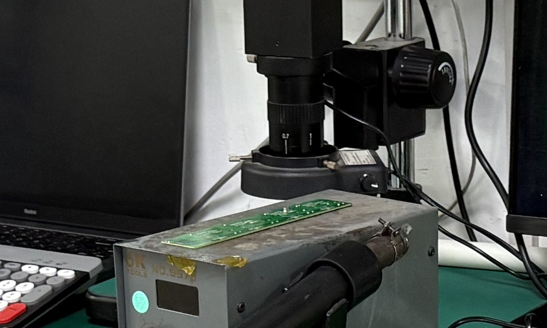
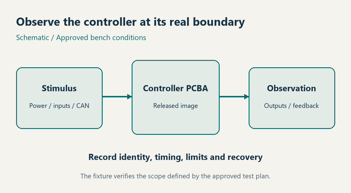
Write bench tests around required state transitions and independently observed outputs. For every test, record the input configuration, expected response, measurement point, timing limits, recovery condition, and acceptance owner. Curtis’s 1244 controller manual documents model-specific interlock, contactor, and diagnostic behavior. It illustrates the need for an explicit sequence. Use the released requirements for your own controller to define its bench behavior.
| Condition | Evidence to capture | Decision supported |
|---|---|---|
| Power-up and configuration load | Supply condition, image identifier, initialization result and defined output state | The unit starts in the required configuration and state. |
| Valid operating request | Applied input, command output, independently observed feedback and timing | The required input-to-output path is exercised. |
| Specified inhibit or missing prerequisite | Input state, output behavior and diagnostic indication under approved conditions | The documented inhibit behavior is observable. |
| Approved fault simulation and recovery | Stimulus, response, retained indication and required reset or recovery sequence | The defined bench case meets its acceptance criteria. |
Specify the load representation and what it can establish. An output driving a resistor may demonstrate a narrow electrical function while a coil or drive interface introduces different behavior. The design authority should approve representative fixtures and any controlled fault simulations. Record limits on what the setup verifies. The manufacturing test coverage planning covers the wider requirement-to-method mapping needed to combine inspection, electrical checks, and functional tests.
Include the test fixture and software revisions in every result, together with calibration status where the measurement depends on it. If instruments provide separate logs, align them with a known timing reference and document measurement uncertainty. Preserve observed values where useful alongside the pass/fail outcome. A log with only a green status cannot explain whether the correct configuration, load, or stimulus was used.
Prove the released configuration before increasing quantity
Make the first production build representative of the released process and demonstrate that its tests detect the intended cases. Review the fabrication data, supplied part identities, assembly drawing, software image, fixture, and acceptance limits together. Establish a reference unit or approved reference data. Where the project permits, use controlled challenge cases to confirm that the fixture reports the expected failure and identifies the tested unit.
OrinewPCB’s video discusses risks that appear when a working prototype moves into a production batch. For a tow tractor controller, the corresponding handover should control parts, process files, configuration selection, and test evidence before the quantity increases.
Define what reopens a review. A component alternative, board revision, programmed image, coating process, enclosure arrangement, or fixture change may affect previous evidence. Name the change owner and require a disposition before using the new configuration. Keep any additional vehicle or qualification work assigned to the responsible team.
Send a complete build package with named acceptance records
Release the order when files, delivered configuration, acceptance criteria, and record ownership agree. Include fabrication outputs and stackup, assembly drawing, BOM and approved alternatives, placement data, quantities by option, programming responsibility, protection notes, and the test matrix. A full-turnkey PCB assembly scope can coordinate fabrication, sourcing, assembly, and agreed testing against that same baseline.
For a controller ready for manufacturing evaluation, send the released fabrication and assembly package with the required serial or lot records, fixture ownership, and approval contact. The review can clarify material availability, process feasibility, test deliverables, and quotation assumptions. The resulting purchase package should let both parties trace each delivered board to the exact build and evidence they agreed to accept.
Latest Blog

Contact Info
Phone: +86-755-82882936
Email: [email protected]
WhatsApp: +86-13570802455
Wechat: +86-13570802455
Address: 2nd floor,D Bldg.,Electric Link Technology Bldg.,Gongming,Guangming New Dist.,518106 Shenzhen, China
