
PCB Tooling Holes: Datums, Pin Fit, and Panel Release
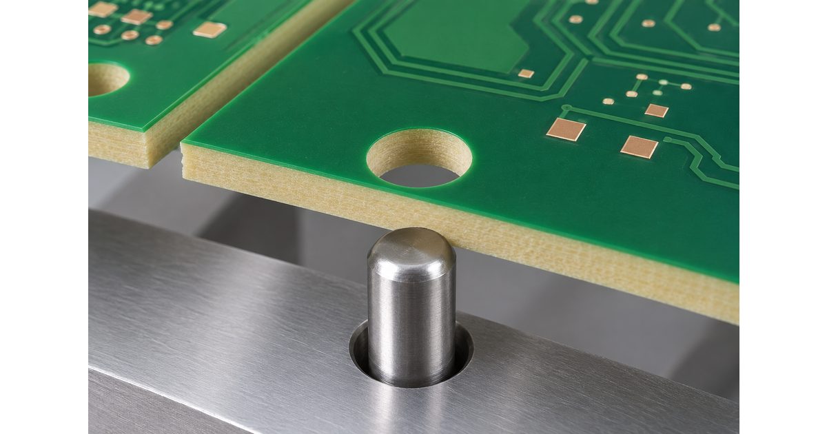
Table of Conent
Table of Conent
PCB tooling holes provide mechanical references for a manufacturing, assembly, or test fixture. Their usefulness depends on the hole geometry, location, mating locator, and the stage at which they are used. Adding an arbitrary hole near a board corner does not establish a repeatable locating method.
For engineers and buyers, the practical task is to define the interface between the PCB and the equipment without confusing process references with product mounting holes. This guide explains how to specify the intended function, coordinate the panel, review tolerance and access, and release consistent fabrication files.
Assign a process purpose to each hole
Identify the operation that uses the hole and the party responsible for the mating fixture. The reference may serve a panel-handling arrangement, an assembly tool, or a test setup. Do not assume one hole automatically meets every downstream process requirement.
Altium’s tooling-hole overview discusses the distinction between manufacturing references and mounting features. Use that distinction in the release: state which holes are process features and which belong to the finished product’s mechanical interface.
If a hole has more than one intended use, review the combined requirements. A location that works for a temporary fixture may not provide the required enclosure fit or assembly access. Treat shared use as a design decision to validate, not a convenience assumed during purchasing.
Separate mechanical location from optical registration
A locating pin and a machine-vision target work through different interfaces. The pin engages the physical hole, while a fiducial provides a recognizable optical feature. Their drawings, access needs, and acceptance criteria should not be treated as interchangeable.
The PCB fiducial marks guide explains the optical reference side of the process. A fixture can use tooling holes while printing or placement uses fiducials. Define which reference establishes which part of the setup so the two systems agree on the board orientation.
Also distinguish tooling holes from ordinary plated vias. A via exists to make an electrical connection. Reusing one as a locator changes the mechanical interaction with that feature and requires an explicit review of its geometry and function.
Decide whether the reference belongs to the board or panel
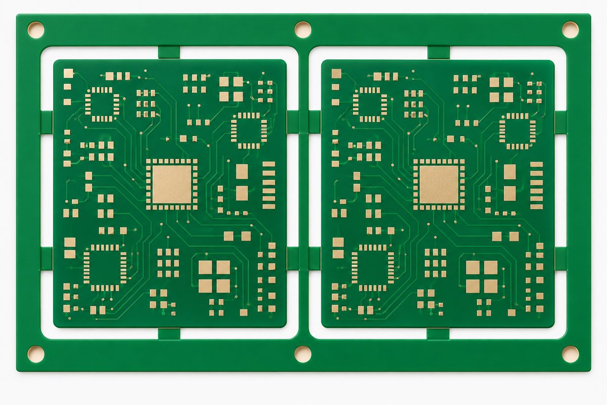
A hole on a removable panel rail may serve an operation performed before separation. A hole needed for a later individual-board test or fixture must still exist when that operation occurs. Map the required process stages before placing references in material that will be discarded.
Eurocircuits’ customer-panel guidance describes panel borders as space for tooling and other process features. Its specific panel rules belong to its own service. The transferable point is to plan the manufacturing border and its function rather than assume that the final board outline includes all necessary references.
The PCB panelization guide provides the broader context for rails, tabs, and separation. Discuss who supplies panel-level holes and who approves any change to the circuit’s own mechanical references.
Specify diameter and locator fit as a coordinated interface
Define the required finished hole and its permitted variation. Coordinate it with the actual pin or locator specification, including the intended engagement and handling method. A nominal hole diameter without a tolerance or mating reference can leave the fixture designer and fabricator working from different assumptions.
Do not choose an unnecessarily tight fit simply because it appears more precise. Review the range of the manufactured hole and locator together and ask whether boards can be loaded and removed without forcing or damage. A loose fit can affect registration; an overly restrictive fit can obstruct the process.
Where several locators are used, ask the fixture designer how the arrangement accommodates the relevant variation while establishing the required position. Do not assume that adding more tightly fitting pins always improves location. The whole fixture relationship needs review, not only each nominal diameter.
State plating status and copper clearance explicitly
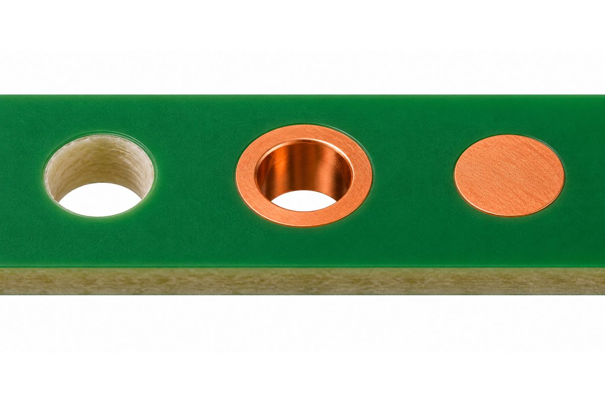
Many mechanical locating designs use nonplated holes, but the required construction must be stated rather than inferred from a name. If a plated hole is intentionally selected, account for the finished interface and its other functions. The fabrication data should make the intended PTH or NPTH classification clear.
Review copper clearance around the hole on every relevant layer. A clean opening on the outer-layer display does not establish that an internal plane or track has the intended isolation. Include the manufacturer’s positional and construction allowances in the clearance review.
Do not rely on the visual absence of an outer copper pad as the only instruction. Confirm the drill data and drawing agree on the hole type, final size, and location. Resolve any contradictory classification before the manufacturer assigns the feature to a production process.
Preparing a fixture-based prototype? Send the PCB files, mechanical drawing, hole requirements, mating-locator information, quantity, and process purpose through the PCB engineering and quotation request. Ask for review of the proposed construction and mechanical interface before the order scope is finalized.
Locate the holes from a useful datum system
Define the relationship between the tooling holes and the features that must be located. State the coordinate reference and the required location controls on the drawing. A set of dimensions measured independently from convenient edges may not describe the registration that the fixture actually needs.
Review the board profile, hole positions, and fixture references together. The fabricator and fixture designer should agree on how the requirements are interpreted and evaluated. Do not replace a controlled datum relationship with an unlabeled screenshot or a measurement taken from a prototype.
Make orientation clear. If the mating arrangement must prevent an incorrect setup, specify the agreed locating or identification approach. Avoid introducing an asymmetric hole pattern as an informal late change without updating the corresponding machine or fixture documentation.
Check access, support, and the complete loading path
Verify that the locator can enter the hole in the actual assembly condition. Components, leads, fixtures, and enclosure features may obstruct access from one face even when the hole itself is clear. Review the approach, engagement, and removal path rather than only the final seated position.
Keep locating and support requirements distinct. A pin can establish a reference without providing adequate support for another process load. Ask which surfaces support the board, where clamps act, and whether those contacts remain compatible with the component layout.
For panel-level holes, review their position relative to rails, routing channels, and support tabs. Leave the manufacturer enough information to preserve the intended reference during handling and separation. A hole near a removable feature can cease to be useful if the panel plan changes.
Release drill data and mechanical documentation together
Eurocircuits’ mechanical-layer guidelines describe the role of profile information, special tolerances, and PTH/NPTH indications. A clear mechanical drawing supports the drill data; it should not contradict or silently replace the production files.
Include the released board revision, hole coordinates, classification, finished-size requirements, and applicable tolerances. Identify the fixture or interface document where necessary. For panelized delivery, distinguish individual-board features from holes added to the manufacturing frame.
Preview the exported data and compare it with the drawing. Confirm units, origin, orientation, and the population of holes. A footprint revision or panel conversion can change the output even when an older mechanical PDF still shows the intended arrangement.
Agree on verification and supplier responsibilities
Compare the proposed board with the PCB manufacturing capabilities, then obtain project-specific confirmation of the tooling-hole requirements. A general capability statement does not qualify a particular pin-fit and positional-tolerance combination.
Define the evidence needed for acceptance. Dimensional checks and fixture-fit evaluation answer different questions, and a successful fit on one sample does not automatically establish the required production tolerance. Agree on measurement references, sample scope, and any records needed for the build.
If the panel holes, fixture interface, or inspection scope remain open, attach the current files and list those questions in the tooling-hole PCB quotation request. Ask for engineering review so the quotation distinguishes approved requirements from remaining assumptions.
Review changes before repeating the order
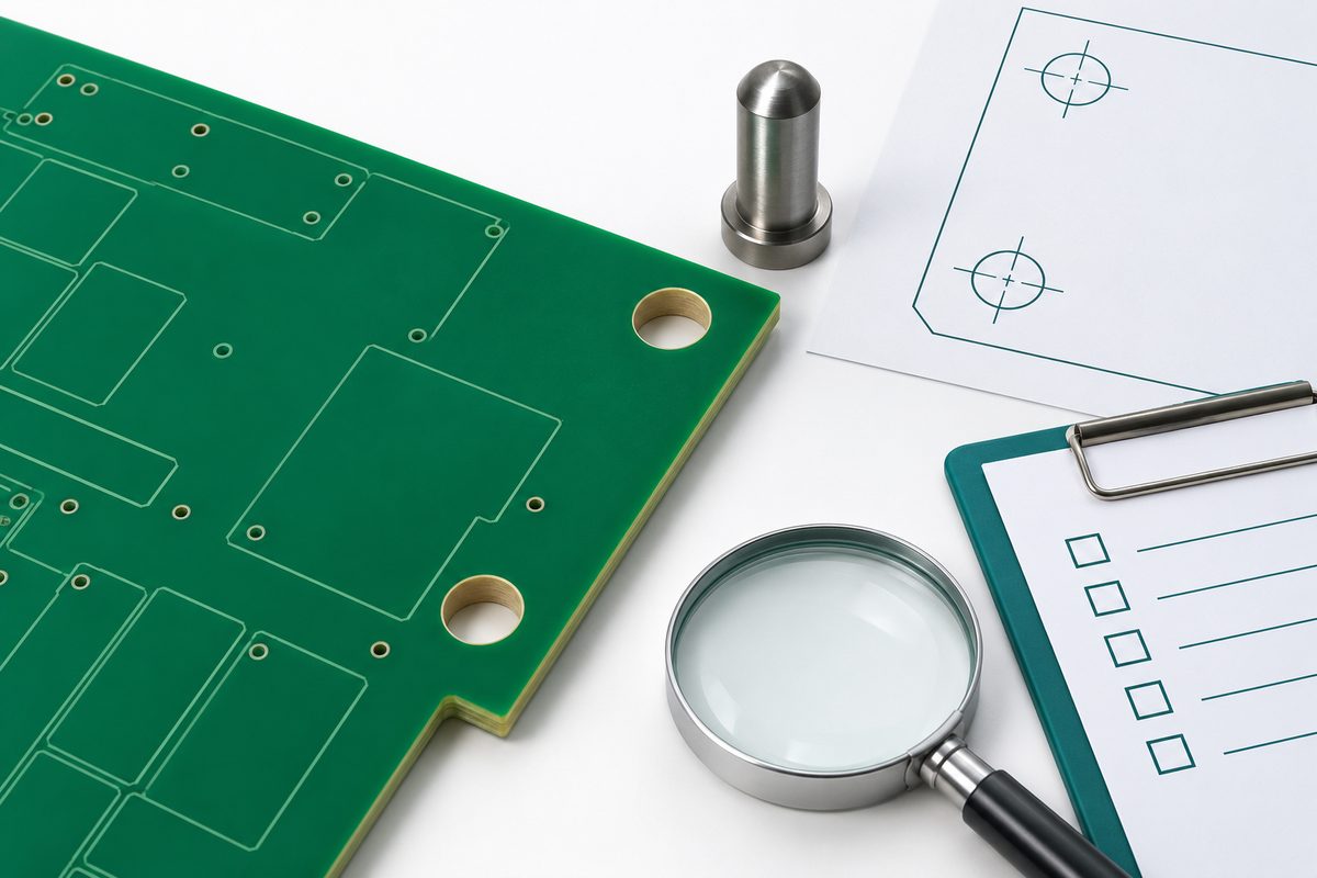
As a hypothetical example, moving the board outline while retaining the old hole coordinates can alter the relationship between a locator and a supported edge. The holes may still be drillable, yet the fixture can reference the board differently. Review the interface after profile, panel, or datum changes.
Apply the same control to plating changes, component moves that affect access, and fixture revisions. Keep the accepted board and fixture requirements linked so a repeat build follows the approved combination instead of relying on an old sample’s appearance.
Conclusion
PCB tooling holes are mechanical process interfaces. Define their purpose, board or panel ownership, finished geometry, datum relationship, access, and verification requirements together. Consistent drill data and drawings help the supplier quote and manufacture the intended feature without guessing its role.
Ready to review the build? Submit the released PCB files, mechanical and panel drawings, locator requirements, quantity, schedule, and inspection scope through the online PCB RFQ form for engineering and quotation review. Highlight the holes that serve critical process references so their requirements can be assessed before production.
Latest Blog
Contact Info
Phone: +86-755-82882936
Email: [email protected]
WhatsApp: +86-13570802455
Wechat: +86-13570802455
Address: 2nd floor,D Bldg.,Electric Link Technology Bldg.,Gongming,Guangming New Dist.,518106 Shenzhen, China