
Bare-Board PCB Electrical Testing: Netlists, Coverage, and Reports
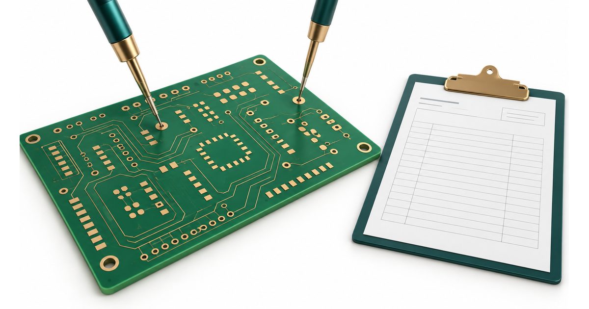
Table of Conent
Table of Conent
Bare-board PCB electrical testing checks a manufactured board’s conductive networks before components are assembled. For a buyer, the key issue is not simply whether the shipment is marked “electrically tested.” It is whether the test used the correct design revision, addressed the agreed connectivity requirements, and produced traceable evidence for the delivered boards.
Three questions make an RFQ stronger: Which data defines the intended connections? What test scope and access are achievable? What records will establish the result? This guide connects those questions without prescribing universal resistance limits, test voltages, or machine capabilities.
Define what the electrical test must establish
Continuity testing evaluates intended connections; isolation testing evaluates separation between nets that should not be connected. Opens and shorts are therefore different test concerns. A report should identify the agreed test requirements rather than compress both into an unexplained pass label.
The official IPC-9252B scope and contents preview describes a framework for selecting test equipment, parameters, source data, and fixturing for unpopulated boards. It also explains that electrical testing does not establish all physical requirements or guarantee assembly suitability. The preview is not the complete specification; confirm the contractually applicable document and edition.
Keep ordinary bare-board connectivity testing separate from assembled-board in-circuit testing and functional testing. A bare board has no populated circuit to operate. If the construction contains embedded components or other special structures, explicitly identify them and agree the applicable evaluation rather than assuming a conventional test program covers them.
Likewise, do not treat an electrical pass as confirmation of every conductor dimension, solder-mask feature, surface finish, or reliability requirement. Those need the appropriate inspection and qualification evidence.
Keep design intent independent of manufacturing data
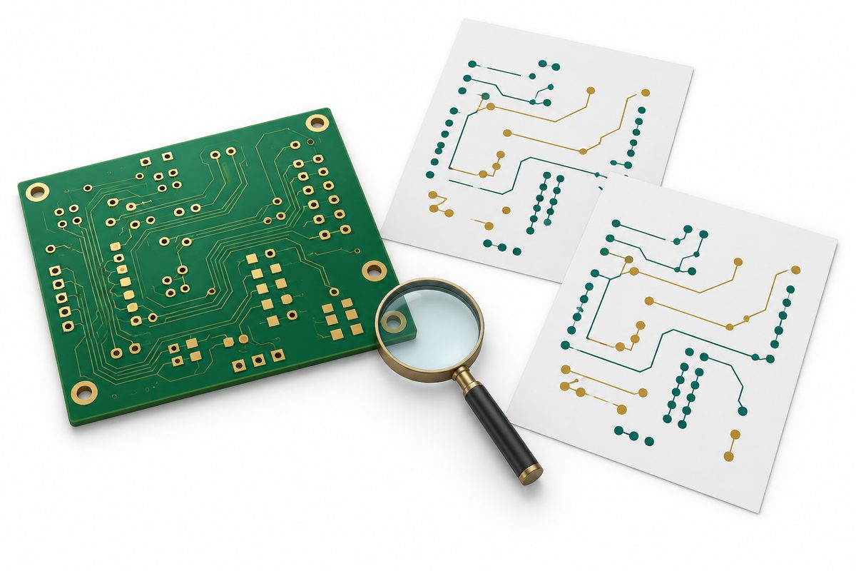
A netlist identifies which connection points belong together. For manufacturing review, distinguish the released design’s connectivity from a netlist extracted from fabrication artwork. Both are useful, but they serve different roles when checking whether the supplied geometry matches the intended circuit.
Altium’s IPC-D-356 netlist guidance describes supplying electrical connectivity information alongside fabrication outputs and comparing imported design connectivity with extracted manufacturing data. Confirm the format supported by your supplier instead of assuming every export is accepted unchanged.
As an engineering safeguard, ask where the test program’s reference came from. Testing manufactured copper against a reference derived solely from the same incorrect artwork may not independently establish the intended design. A comparison with released design connectivity provides a separate review opportunity, but it still depends on correct revision control and interpretation.
The PCB design-to-manufacturing checklist provides context for a controlled file handoff. Export the netlist and manufacturing package from the same released revision, record filenames, and identify any special connectivity rules in the drawing or accompanying notes.
Resolve differences before generating the test program
A comparison mismatch is a review item, not automatic proof that the manufactured board is defective. Check layer mapping, coordinate conventions, drill information, revision alignment, and any intentional connection features. Ask the supplier to identify the specific discrepancy rather than returning only a generic “netlist mismatch” message.
Keep the decision tied to a location and controlled file set. If the design is corrected, issue a complete revised package. If the comparison is explained by an intentional feature, document the explanation and the approved treatment in the test-data review.
Do not silently suppress a mismatch to release the order. An approved exception should identify what was reviewed, why it is acceptable, and which revision it applies to. Approval for one design must not become an undocumented standing exception for later revisions.
Send your fabrication files, released netlist, and electrical-test requirements for a manufacturing quote review. Include any intentional connectivity exceptions so data and test-scope questions can be resolved before production.
Review access separately from equipment selection
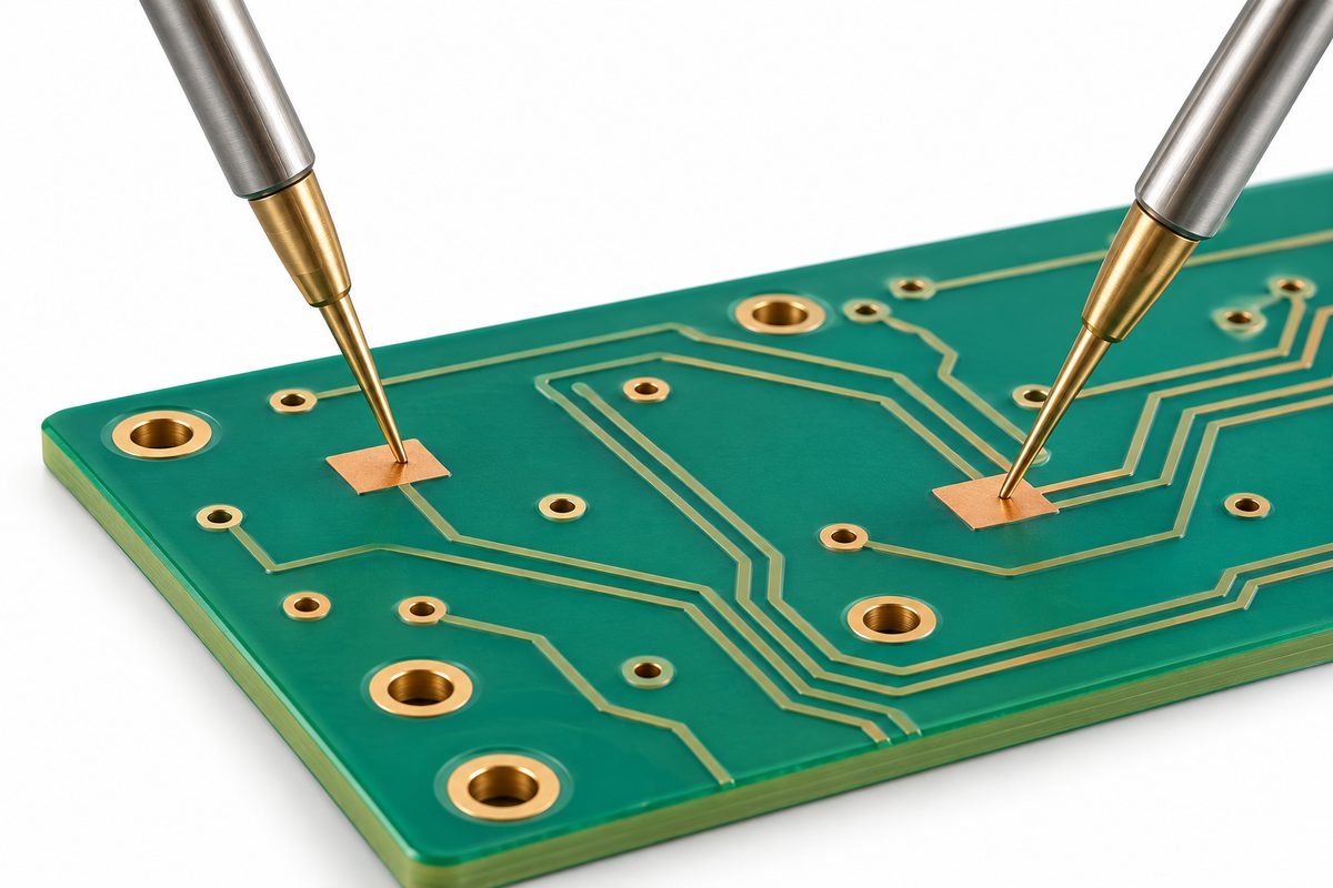
Ask which surfaces and features the proposed system can contact. Identify nets with limited exposed access, unusual pad geometry, or structures requiring a special approach. The existence of a copper feature in design data does not by itself show that a physical probe can reach it reliably.
Eurocircuits’ electrical-test overview describes using flying probes for opens and shorts and notes the setup advantage of avoiding a dedicated fixture. This is manufacturer background, not evidence that AssyPCB owns the same equipment or uses an identical process.
Discuss the proposed approach in terms of test scope, setup effort, repeat orders, and access. Do not choose solely by the machine name. Ask the supplier to explain whether a moving-probe or fixture-based arrangement is appropriate for your board and quantity, and which assumptions affect the quotation.
If artwork changes are proposed to improve access, review their electrical and mechanical implications before approval. Added features or modified mask openings should remain under design control. A convenient contact point is not permission for an unrecorded design change.
Specify coverage in words the report can support
Define what “tested” means for the order. Ask how continuity and isolation requirements are implemented, what areas or structures are outside the agreed scope, and how exceptions are recorded. A percentage without its denominator is not a useful coverage statement.
Distinguish the number of boards tested from the extent of testing on each board. A claim about all shipped boards does not automatically explain which networks, connection points, or isolation relationships were evaluated. Keep the shipment requirement and the test-program requirement separately visible.
For any special testing, state the required method and parameters through the approved specification. Do not derive a test voltage from the product’s operating voltage or import a resistance limit from a different construction without technical review. Where the supplier proposes alternatives, request a written scope comparison.
Record approved exclusions explicitly. If a feature cannot be evaluated by the proposed setup, identify it before accepting a broad electrical-test certificate. Agree the additional evidence or alternative evaluation needed rather than allowing a missing item to disappear from the report.
Retain traceability through failures and retests

A useful shipment record links the board number and revision, lot, tested quantity, test-data revision, method, agreed parameters, results, and exceptions. Confirm the level of board identification and record retention required by the order before manufacturing begins.
If a board fails, distinguish an observed electrical result from the investigation of its cause. Contact quality, test data, and the board itself may need review. Do not label an unexplained retest pass as proof that the original finding was false.
Document retesting and any approved repair or disposition. Keep the original failure record associated with the later result, including the reason for the retest. This creates a more defensible evidence chain than overwriting the first result with the final pass.
Request a project review with your controlled drawing and required electrical-test report fields. Include traceability, retention, and exception-handling expectations so they can be reflected in the manufacturing and quotation scope.
Use other inspections for other questions
When an investigation concerns internal construction, our PCB microsection analysis guide explains how selected sections support structural observations and measurements. An electrical result and a microsection report are complementary records, not interchangeable proof.
Keep impedance characterization, surface-finish verification, dimensional inspection, and product reliability evaluation in their own agreed scopes. A board may need more than connectivity evidence to satisfy the project’s requirements. The purchase package should identify those requirements rather than expecting the phrase “E-test” to include everything.
Conversely, a good-looking board or a satisfactory section is not a replacement for the specified electrical test. Review each requirement against the evidence designed to address it.
A hypothetical wrong-reference example
Consider a design release in which two intended separate nets are accidentally joined in exported artwork. This is a hypothetical example, not an AssyPCB production case. If manufacturing and the electrical reference both follow that artwork, a result consistent with the reference does not independently prove the intended separation.
The engineering team first compares the released design connectivity with the artwork-derived connectivity and resolves the mismatch. It then issues the corrected controlled package and confirms the test-data revision. The important lesson is reference integrity: a test result can only be interpreted in relation to the data and requirement it evaluated.
Close the RFQ with a controlled evidence package
Provide fabrication files, drill data, released connectivity information, board revision, applicable electrical-test requirements, special structures, and expected records. State delivery quantity, repeat-order assumptions, and who approves exceptions. Ask the supplier to identify missing data, access concerns, and any separate inspection scope before release.
The published PCB manufacturing capabilities are a starting point for project discussions, not confirmation of every custom test method or numerical limit. Confirm the actual construction and verification arrangement for the order.
Submit your PCB files, netlist, and electrical-test evidence requirements for a project-specific quote. Correct reference data, explicit coverage, and a traceable report give engineering and purchasing teams a stronger basis for acceptance than an unexplained electrical-test mark.
Latest Blog

Contact Info
Phone: +86-755-82882936
Email: [email protected]
WhatsApp: +86-13570802455
Wechat: +86-13570802455
Address: 2nd floor,D Bldg.,Electric Link Technology Bldg.,Gongming,Guangming New Dist.,518106 Shenzhen, China