
PCB Solderability Testing: Methods, Conditions, and Supplier Evidence
Table of Conent
Table of Conent
PCB solderability testing asks whether the specified board surface will wet with solder under defined conditions. It is useful when qualifying a surface finish, agreeing incoming inspection, investigating stored inventory, or separating a bare-board concern from an assembly-process problem. A report is only meaningful when its specimen, method, materials, conditioning, and acceptance requirement are identified.
For engineers and buyers, the goal is a reproducible decision, not an unexplained “pass” certificate. This guide focuses on the questions to settle before testing, the differences between visual and force-based evidence, and the records to request from a supplier. It does not prescribe a universal solder temperature, exposure time, storage life, or acceptance percentage.
Define the surface and the question first
A solderability requirement should identify what is being evaluated: surface-mount attachment lands, other exposed conductors, plated-through holes, or a representative coupon. Keep a bare-board requirement separate from a component-lead requirement. A component test result cannot automatically establish that the PCB finish will accept solder.
The official IPC J-STD-003D contents preview identifies printed-board solderability methods, specimen requirements, conditioning topics, and evaluation sections. It distinguishes visual acceptance tests from force-measurement tests. The preview is a useful scope reference, but it is not the complete procedure or acceptance specification; use the agreed full document for execution.
Write the purpose in plain language before selecting a method. Incoming acceptance asks whether the delivered lot meets the order requirement. A qualification comparison asks how defined constructions or finishes perform under an agreed evaluation. A failure investigation asks why a particular assembly observation occurred. These purposes may need different specimens and records.
A purchase drawing that says only “good solderability” leaves too much unresolved. Specify the applicable standard and revision, the evaluated features, conditioning where required, acceptance basis, sampling plan, and report expectations. Agree these items before production rather than after a shipment is disputed.
Choose evidence that matches the feature
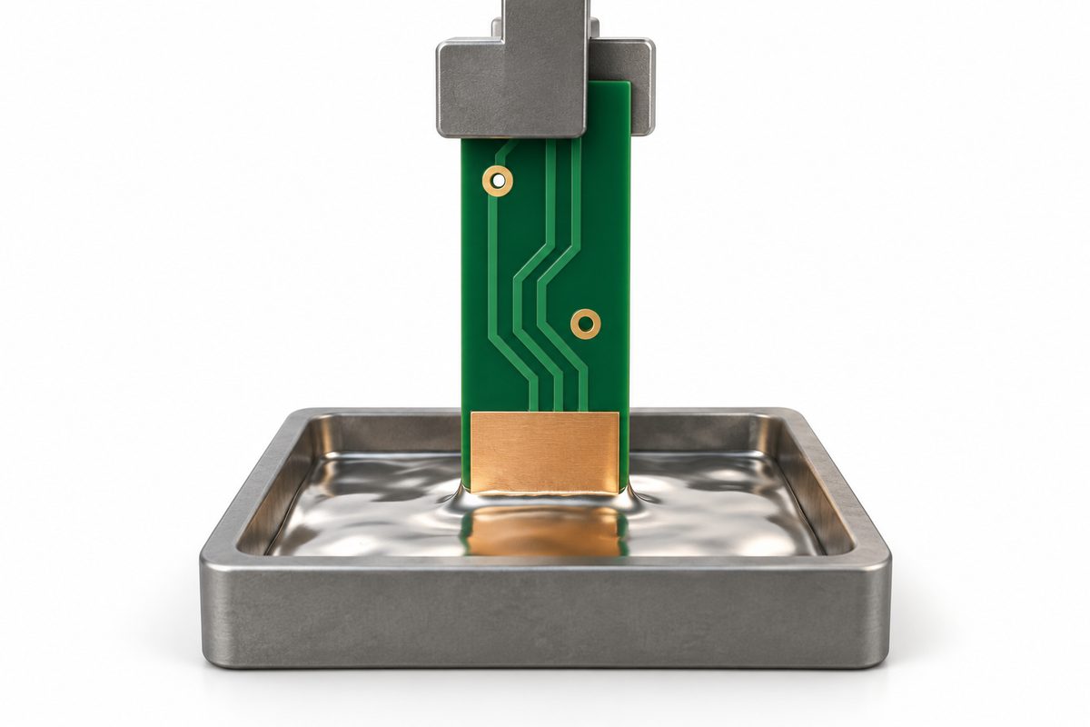
Visual methods and wetting-balance methods answer related questions but do not provide interchangeable evidence. A visual evaluation examines the tested surface after the prescribed solder exposure. A wetting balance records force behavior over time during a controlled interaction with molten solder. The selected technique must be applicable to the specimen and its finish.
GEN3’s solderability testing overview describes visual dip-and-look, solder-spread, and wetting-balance approaches. Use this as general background, not as authorization to substitute one technique for a contractually specified method.
For surface lands, ask which features are included in the evaluation and how they are represented by the sample. For plated-through holes, ask how hole-related solderability is assessed. A photograph of a well-wetted surface pad is not, by itself, evidence that the relevant hole surfaces were evaluated.
Do not select a method solely because its result is easy to summarize. A numerical curve without a defined interpretation is no more decisive than an unscaled photograph. Ask the laboratory which outputs support the stated requirement and whether any specimen limitations need to be documented.
Control the conditions before comparing results
Two reports using the same method name can still describe different evaluations. Review the solder alloy, flux identity and condition, bath or test-material control, temperature, exposure, specimen orientation, and conditioning history. Record the actual procedure rather than relying on the laboratory’s usual setup.
Do not quietly change flux or exposure to obtain a favorable outcome. If a diagnostic trial intentionally changes a condition, label it as a separate investigation and retain the original result. An agreed acceptance test and an exploratory assembly trial should not share a single ambiguous pass statement.
For visual evidence, request the inspected features, image identification, and the evaluation rule. For force-based evidence, request the raw trace, units, specimen geometry, and reported metrics. Preserve the connection between the raw output and the final judgment so another qualified reviewer can follow the decision.
The equipment manufacturer GEN3 explains solderability as surface wetting with molten solder. An instrument can help collect evidence, but its availability does not establish that a particular test setup, acceptance threshold, or specimen is correct for your order.
Send your board files, finish specification, and solderability requirements for a manufacturing quote review. Identify whether you need routine delivery evidence, a qualification evaluation, or help defining a disputed test condition so the requested scope can be discussed.
Keep storage and handling history traceable
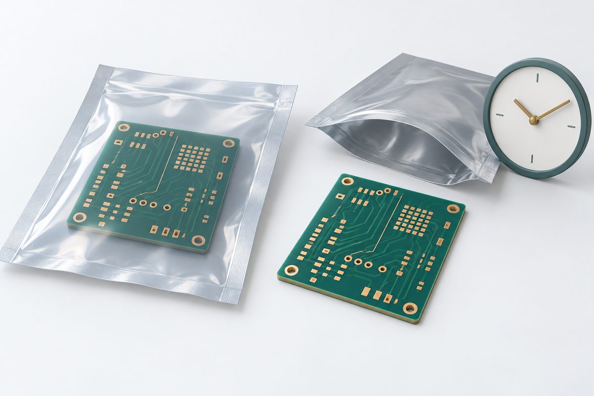
Record the finish, fabrication date or lot reference, packaging condition, opening date, and relevant handling history. These records help establish what was tested and whether it represents the delivered or stored inventory. An unknown history should be reported as unknown, not reconstructed from an assumed shelf-life figure.
Ask the supplier for finish-specific storage and handling instructions. Avoid treating all finishes, packaging systems, or environmental conditions as equivalent. A generic expiration date taken from a different product is not a sound basis for accepting or rejecting your boards.
Keep samples protected and identified while the investigation is arranged. Document any cleaning, baking, rework, or additional thermal exposure before testing. If treatment is proposed, request an approved product-specific instruction and agree how treated and untreated samples will be compared.
Do not clean or condition the entire suspect lot merely to make the first test easier. Preserve representative untreated material where feasible, so the original condition remains available for investigation. The decision to release or reprocess inventory should follow evidence and the agreed disposition authority.
Separate solderability from assembly performance
A solderability test is not a complete assembly-process qualification. A board result alone does not resolve solder-paste printing, thermal profile, component termination, placement, or equipment questions. Conversely, a poor joint observed on an assembly does not automatically prove that the bare-board finish caused it.
Collect the assembly observation precisely: affected features, location, lot, process stage, material identities, and available inspection records. Compare boards and components independently where appropriate. Keep the investigated symptom separate from the proposed cause until evidence supports that cause.
The reflow soldering guide provides context for discussing assembly processing alongside the board evaluation. When reviewing results, distinguish the conditions used in the laboratory from those used on the production line instead of assuming they are equivalent.
Our PCB fabrication troubleshooting guide offers a framework for assembling supplier evidence and checking corrective actions. Use it to organize the investigation, not as a substitute for the applicable solderability procedure.
Request a report that supports supplier acceptance

A useful report identifies the board and revision, lot, tested surface, sample source, method and revision, conditioning, test materials, relevant settings, equipment identification, individual observations, and acceptance basis. It should explain any deviation from the requested method and identify who approved that deviation.
Request individual results instead of only an average or a lot-level pass label. The sampling record should show which pieces were selected and how they relate to the shipment. Do not infer that every feature or every board was tested when the report describes a small representative sample.
Images should identify the sample and feature being shown. Curves should retain their units and time reference. If the report contains a derived metric, ask how it was calculated and which requirement it addresses. Unlabeled outputs can be useful exploratory notes, but they are weak acceptance evidence.
Agree the reporting scope during quotation. Extra conditioning, special samples, independent laboratory work, or additional analysis may require a separate arrangement. Ask for the proposed scope and schedule rather than assuming these services are automatically included with fabrication.
Request an engineering and quotation review with your controlled drawing and required test-report fields. Include the intended alloy, assembly route, quantity, and delivery condition so manufacturing and evidence requirements can be considered together.
A hypothetical disagreement between two tests
Consider a buyer who receives a visual solderability pass report but later obtains a concerning force-based result from stored boards. This is a hypothetical example, not an AssyPCB production case.
The first step is to compare specimens, conditioning, test materials, and acceptance requirements. The reports may answer different questions or represent different inventory histories. The teams then agree a controlled comparison, retain the original records, and define which requirement governs disposition. Neither result should be discarded simply because the other seems more favorable.
Turn the test requirement into a clearer RFQ
Include the board files, revision, surface finish, evaluated features, applicable standard, conditioning requirements, sampling, and expected report. Specify any customer-controlled acceptance rules and identify who may approve deviations. Ask which additional information the supplier needs before accepting the requested scope.
The published PCB manufacturing capabilities are a starting point for construction discussions, not confirmation that a custom laboratory method or qualification program is included. Confirm the exact testing and reporting arrangement for the project.
Submit your PCB files, assembly requirements, and solderability evidence needs for a project-specific quote. A defined method and a traceable report help both parties make a defensible decision without relying on an unexplained pass label.
Latest Blog
Contact Info
Phone: +86-755-82882936
Email: [email protected]
WhatsApp: +86-13570802455
Wechat: +86-13570802455
Address: 2nd floor,D Bldg.,Electric Link Technology Bldg.,Gongming,Guangming New Dist.,518106 Shenzhen, China