
Solder Preforms for PCB Assembly: Volume, Flux, and Process Selection
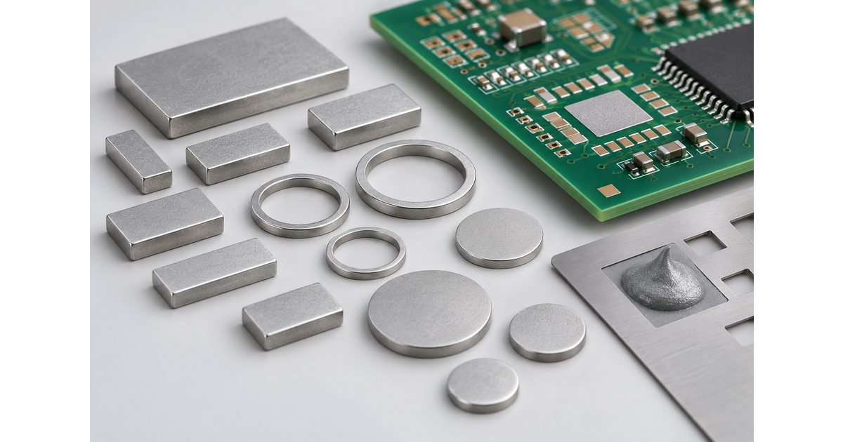
Table of Conent
Table of Conent
Solder preforms are solid pieces of solder alloy made in defined shapes and dimensions. They offer a way to place a controlled quantity of metal at a joint. In PCB assembly, a preform may supplement solder paste or support another qualified soldering process. It is not automatically a replacement for paste, flux, or a suitable land pattern.
The useful decision is whether a preform solves a specific joint-volume or process problem without creating new placement, wetting, clearance, or inspection problems. This guide gives engineers and buyers a practical framework for selecting the material, defining its use, and preparing an assembly RFQ.
Start with the joint requirement, not the solder shape
Identify the joint that needs additional control. Is the concern insufficient metal, incomplete through-hole fill, a large termination, or a specialized interface? Record the geometry and the evidence behind the proposed change. A visibly small fillet is not, by itself, enough to decide that every similar joint needs more solder.
First review the existing land pattern, component termination, paste deposit, and soldering process. If poor wetting or a misplaced component is the main problem, adding alloy may not address the cause. A preform is a material and process choice, not a universal defect-repair method.
Define the intended result in terms the assembler can evaluate. State the applicable joint requirements and which changes are permitted during development. This keeps an experiment with solder volume separate from an uncontrolled change to the released assembly.
Understand how a preform can supplement paste
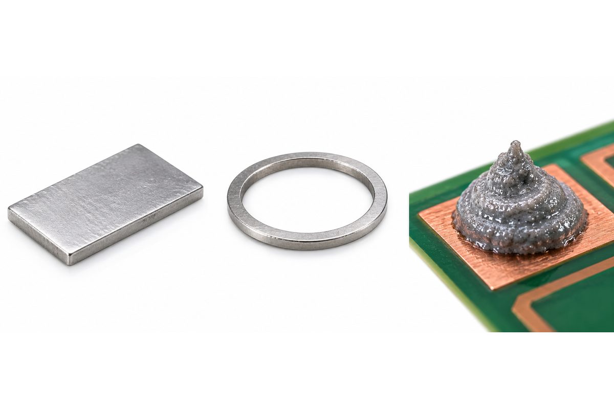
Indium Corporation’s PCB assembly preform overview describes a product family of flux-free rectangular alloy pieces used with solder paste. In that defined application, the preform adds metal and uses the paste’s flux during reflow. That example demonstrates supplementation; it does not establish that every alloy and paste combination is compatible.
Adding a placed preform can be an alternative to increasing a printed deposit at selected locations. Review both approaches against the full board. A stencil change intended to increase solder at one joint may affect other deposits, while a preform adds its own material supply and placement requirements.
The SMT stencil design guide provides the broader printing context. For a preform-assisted joint, define which part of the solder quantity comes from printing and which comes from the solid alloy piece. Do not leave the combined quantity to operator judgment.
Translate dimensions into metal volume carefully
A rectangular preform’s nominal volume follows its length, width, and thickness. A ring’s nominal volume depends on its outer diameter, inner diameter, and thickness. If specifying quantity by mass, use the relevant alloy information and supplier specification rather than assuming all solders have the same density.
Keep nominal geometry separate from the permitted dimensional or mass variation. Ask which quantity the supplier controls and how it relates to the required joint. An extra piece or a thickness substitution changes the amount of metal even when the placement location is unchanged.
Solder paste is not the same as an equal geometric volume of solid solder. Its formulation includes flux and other constituents. Use the selected paste’s data and a validated process basis when estimating the metal contributed by a deposit. Do not compare wet paste volume and preform volume as interchangeable quantities.
More metal is not always better. Review the intended joint space, adjacent features, and the possibility of solder reaching an unintended area. The target is an acceptable connection with repeatable processing, not the largest fillet that can fit under the component.
Select the alloy and flux arrangement together
Choose the preform alloy in the context of the assembly’s material requirements and thermal limits. Check compatibility with the paste, component finish, PCB finish, and soldering method. A visually identical ring from a different alloy is not an approved substitute simply because it fits the same fixture.
Preforms may be supplied with a flux coating or used with a separately defined flux arrangement. Indium’s flux-coated preform information distinguishes coating chemistries and substrate compatibility. Specify the actual material and coating instead of treating “flux-coated” as a complete process recipe.
Clarify residue and cleaning requirements for the finished product. A no-clean designation does not replace a review of the assembly’s operating environment and acceptance requirements. If cleaning is required, confirm access to the relevant surfaces and compatibility of the planned materials.
Define placement and retention before heating
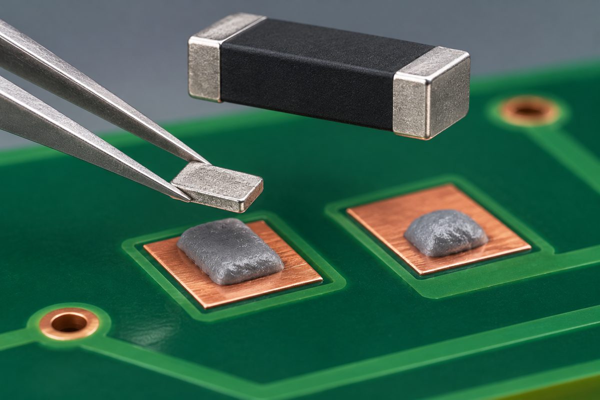
Specify where each preform belongs, how many pieces are used, and how it is oriented. The placement drawing should make it distinguishable from an ordinary component or a loose assembly accessory. Include enough detail that the process engineer can reproduce the intended arrangement without interpreting a prototype photograph.
Review clearance around neighboring lands and component bodies. A preform must be accommodated by the actual joint geometry and assembly sequence. Avoid relying on a piece being pushed into position after nearby components have obstructed access.
Agree on how the material is presented and retained before soldering. Packaging, handling, and placement equipment affect how reliably a small piece reaches its intended location. A supplier’s tape-and-reel offering does not establish that every custom shape can use the same feeder or placement settings.
Preparing a preform-assisted prototype? Send the BOM, assembly drawing, target joints, proposed preform and paste identities, quantity, and inspection requirements through the PCB assembly engineering and quotation request. Ask for review of material compatibility, placement, and process scope before ordering the build.
Validate the soldering process on the actual assembly
The chosen alloy must melt and wet the intended surfaces within a process that the components and board can tolerate. Do not copy an oven setting from another assembly and assume the added metal behaves identically. Evaluate the thermal process using the actual construction and applicable material guidance.
The reflow soldering guide explains the broader assembly step. For preforms, the extra questions concern how the solid piece interacts with the printed deposit, the flux arrangement, and the joint geometry during that step.
Separate solder quantity from other process variables during development. If the paste, preform count, component position, and heating conditions all change together, it becomes difficult to determine which change produced the result. Record trial conditions and retain an approved configuration after the prototype review.
Match inspection to the requirement being changed
Define which evidence demonstrates that the preform-assisted joint is acceptable. Depending on the interface, the evaluation may involve visible solder condition, electrical coverage, or additional examination of hidden features. Agree on methods and sample selection before the prototypes are allocated to other tests.
A continuity result does not establish every internal joint condition. Similarly, a surface photograph does not prove the hidden solder distribution beneath a component. If the project has a voiding, hole-fill, thermal, or mechanical requirement, specify a suitable evaluation rather than assuming the added preform guarantees it.
Use the review to confirm both the intended joint and neighboring features. An increase in solder quantity that fixes one observation but creates an unintended connection elsewhere is not a successful process change. Document the approved material, quantity, placement, and acceptance evidence together.

Prepare a controlled material and RFQ package
Identify the preform part number or controlled drawing, alloy, shape, quantity per joint, flux arrangement, packaging, and handling requirements. State whether it is a purchased BOM item or an assembly consumable controlled by the process documentation. Either approach needs a clear owner and substitution rules.
Include the board and component data, target joint locations, assembly sequence, inspection scope, and prototype quantity. Ask how the proposed work fits the SMT assembly service, with project-specific confirmation for the selected preform process. A general service description is not proof of a qualified material combination.
If the design remains open, list the unresolved volume, coating, or placement questions in the preform-assisted assembly quotation request. Attach the current files so the engineering and quotation review can distinguish approved requirements from development assumptions.
Control substitutions and repeat orders
As a hypothetical example, replacing one rectangular preform with two thinner pieces changes the count and placement process even if their nominal total metal volume is similar. The assembly should not accept that substitution without reviewing handling, flux interaction, and the resulting joint evidence.
For repeat builds, preserve the approved material identities and process documents. Follow the selected supplier’s storage and handling instructions, and retain lot information appropriate to the product requirements. Review changes to the alloy, coating, package, joint geometry, or soldering process before treating the next order as an exact repeat.
Conclusion
Solder preforms can help control metal quantity at selected PCB assembly joints. Select them around a defined requirement, coordinate the alloy and flux, establish repeatable placement, and validate the actual soldering result. Their value comes from a controlled application, not a blanket promise that more solder improves every connection.
Ready to evaluate the build? Submit the PCB files, BOM, assembly drawing, proposed preform specification, quantity, schedule, and test requirements through the online PCB RFQ form for engineering and quotation review. Mark the joints that need additional material control so the proposed process can be assessed clearly.
Latest Blog
Contact Info
Phone: +86-755-82882936
Email: [email protected]
WhatsApp: +86-13570802455
Wechat: +86-13570802455
Address: 2nd floor,D Bldg.,Electric Link Technology Bldg.,Gongming,Guangming New Dist.,518106 Shenzhen, China