
Press-Fit PCB Assembly: Hole Requirements, Tooling, and Evidence
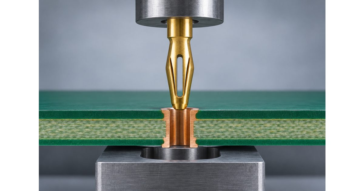
Table of Conent
Table of Conent
Press-fit PCB assembly joins a contact to a plated hole through a controlled insertion process. The connection depends on more than the connector part number: the finished hole, board construction, tooling, support, and seating conditions must work together. A contact that appears fully inserted is not, by itself, evidence that every electrical and mechanical requirement has been met.
This guide explains how engineers and buyers can define a repeatable press-fit build. It focuses on the interface between PCB fabrication and assembly, the information needed for a useful RFQ, and the evidence to agree on before production. Product-specific dimensions and process limits must come from the selected contact’s controlled documentation.
Treat the contact and PCB hole as one system
TE Connectivity’s press-fit technology overview distinguishes solid and compliant press-in zones and describes the contact and plated hole as an interacting system. A compliant contact is designed to deform during insertion. That principle does not make every compliant contact suitable for every hole or board construction.
Start with the exact connector or terminal identity, its application specification, and the approved mating PCB requirements. Do not substitute a similar-looking part without checking the press-in geometry and process requirements. A shared connector housing shape or pin pitch does not establish that the contact system is interchangeable.
Keep the press-fit connection separate from other assembly operations. A board may include soldered components as well as press-fit contacts. The absence of solder at the press-fit interface does not mean the complete assembly has no soldering, thermal exposure, or handling requirements.
Specify the finished hole, not only the drill tool
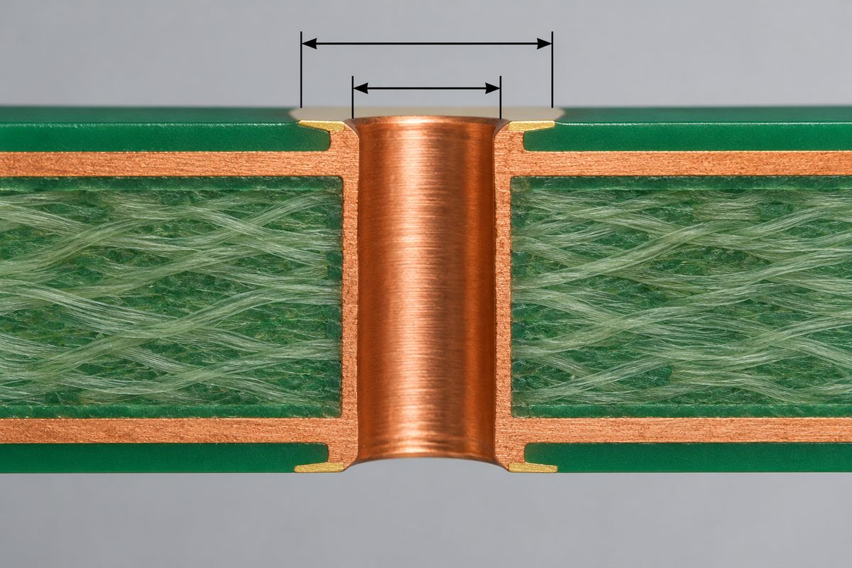
The drilled opening and the finished plated opening are different manufacturing quantities. The contact supplier’s requirement usually concerns the interface it will enter, while the fabricator needs the information required to produce that interface. A drawing that only lists a drill-tool diameter can leave the finished result ambiguous.
For a concrete example of product-specific documentation, Würth Elektronik’s 74622108 press-fit terminal datasheet distinguishes hole requirements for chemical surfaces and HAL. The dimensions belong to that named part; they should not be copied into an unrelated connector design. The example shows why surface finish and finished geometry need to be reviewed together.
Include the applicable hole diameter range, plating requirements, surface finish, and any other construction constraints defined by the contact supplier. Ask the PCB fabricator to confirm its interpretation before the order is released. If the proposed finish changes, review the finished-hole requirement again rather than assuming the same drawing note still applies.
Coordinate board thickness and the contact geometry
Check the permitted board thickness and the position of the press-in zone against the selected component’s application requirements. The interface must be reviewed in the assembled position, including housing seating features and any specified pin projection. Overall pin length alone is not enough to establish the correct installation.
Board thickness also belongs in the mechanical support and enclosure review. Confirm the finished range and measurement basis used by the drawing and supplier. The PCB thickness selection guide explains why nominal thickness should be considered together with tolerances and mating interfaces.
Review nearby features that affect support or access. Components, cutouts, and connector bodies may limit where a fixture can contact the board or where an insertion tool can approach. Resolve those conflicts in the layout or tooling plan before they become an assembly-line exception.
Define alignment and board support before insertion
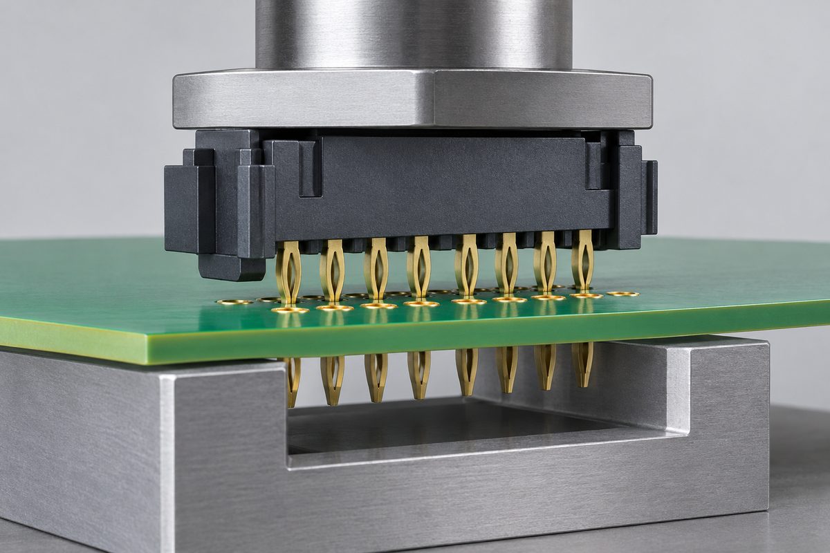
Use a tooling plan appropriate to the component and board. The upper tool must apply load at the intended locations, while the lower support must accommodate the board and any protruding features. The assembly should not depend on unsupported board flex or an improvised tool that loads a fragile part of the connector.
Confirm how the board and connector will be located and how orientation will be checked. A misaligned contact can encounter the board before entering the intended hole. Clear datums, orientation markings, and fixture instructions give the operator and process engineer a shared installation reference.
Do not assume a tool approved for one connector revision is acceptable after the housing or contact changes. Identify the tooling revision and the component combination it supports. For a new design, make access and support part of the engineering review rather than treating the fixture as an accessory ordered after the PCB.
Agree on the controlled insertion process
Identify the applicable seating procedure, process settings, and acceptance limits with the component supplier and assembler. TE’s connector seating equipment overview illustrates how equipment can incorporate press-force measurement and seating controls. Such features are examples of process capability, not evidence that a particular factory owns that equipment or uses it for your order.
Where force and displacement are recorded, agree on how those records will be interpreted for the selected assembly. The useful question is whether the process evidence corresponds to an approved installation, not whether a graph was produced. Limits and alarm responses should be established through the product and process requirements.
A generic force value copied from another connector is not a valid seating recipe. Contact design, pin count, hole construction, and tool behavior belong in the review. Ask which settings are controlled, who approves a change, and what happens when a cycle falls outside the accepted process conditions.
Also review the assembly sequence. Confirm the condition of the plated holes when the press-fit operation takes place and the handling needed before and after installation. Any prior soldering, cleaning, coating, or other operation should be considered against the component and board requirements rather than assumed harmless.
Separate seating evidence from product acceptance
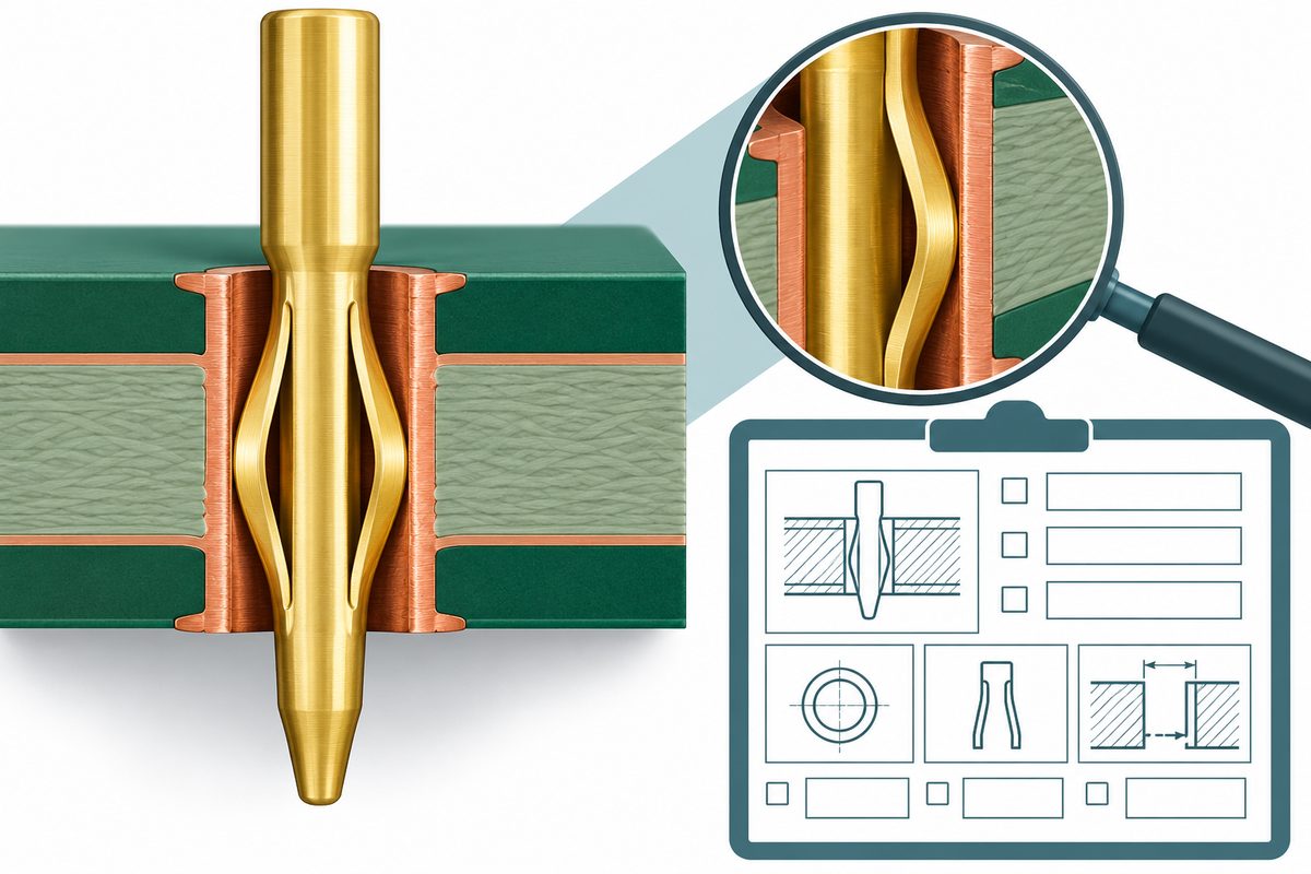
Define the installed position using the component’s drawing and application requirements. Determine how the assembler will check seating, orientation, and visible contact or housing damage. A visual comparison without a defined reference can produce inconsistent decisions between operators or lots.
Electrical testing establishes the connections or functions included in its coverage. It does not automatically establish every mechanical or internal hole condition. Likewise, a retained force record does not replace the electrical test or other evidence required by the product specification. Agree on the combination of checks appropriate to the build.
If internal evaluation, retention testing, or other special verification is required, define the method, sample selection, and reporting scope before production. Some evaluation may affect the sample, so coordinate it with the inspection plan. Do not request a destructive check after all available prototypes have already been allocated to other validation tasks.
Use a clear response when a seating cycle is questioned
Identify and contain the affected assembly while the condition is evaluated. Record the board lot and revision, component identity, tooling revision, process record, and the observed issue. Preserve representative evidence before attempting to correct the installation.
Separate observations from proposed causes. An unusual force profile, incomplete seating, or damaged contact may require different investigation paths. Compare the actual condition with the controlled requirement and review the relevant records before changing the hole design or increasing the press force.
Any removal or replacement must follow the component supplier’s approved rework conditions and the agreed product requirements. Do not assume the same hole and contact can tolerate repeated installation attempts. Clarify whether rework is permitted and which checks are required afterward before using it as a recovery method.
Prepare a release package that crosses the fabrication boundary
For PCB fabrication, provide the production data, board outline, fabrication drawing, material and thickness requirements, surface finish, and the press-fit hole specification. Identify the affected holes clearly so their requirements cannot be mistaken for ordinary component or mounting holes.
For assembly, add the connector or terminal part number, BOM, assembly drawing, installation orientation, applicable application specification, quantity, and process or inspection requirements. State who supplies the components and who is responsible for fixture design, qualification, and maintenance.
The PCB manufacturing-release checklist explains why exports and assembly documentation need a consistent revision. For press-fit builds, include the interface specification in that controlled package so a finished-hole requirement does not remain isolated in a purchasing email.
Preparing a press-fit prototype? Send the fabrication files, contact documentation, BOM, quantity, and installation and inspection requirements through the PCB engineering and quotation request. The package allows fabrication and assembly questions to be reviewed before the order scope is finalized.
Clarify the quotation and repeat-order assumptions
Compare the PCB design with the PCB manufacturing capabilities, and identify the press-fit interface for project-specific confirmation. A general capability page does not establish that a selected contact, hole construction, and installation process have been qualified together.
Separate bare-board fabrication, component sourcing, tooling preparation, insertion, inspection, and testing in the quotation discussion. Ask which one-time preparation activities and recurring checks are included. A low PCB price alone does not describe the complete press-fit assembly scope.
For repeat orders, record which changes trigger another review: connector substitutions, drawing revisions, board construction, finish, tooling, or process settings. Keep approved requirements accessible to purchasing and production so the accepted combination can be reproduced rather than reconstructed from memory.
If the hole, tooling, or inspection scope remains open, include those questions in the press-fit fabrication and assembly quote request with the relevant drawings. Ask for an engineering review of the proposed build and responsibilities before comparing final quotations.
Use the prototype to validate the intended combination
A first build should evaluate the actual board, contact, support, and seating process proposed for production. Record mechanical fit, the required process evidence, and the relevant electrical or functional results. A successful installation on a different board construction is not sufficient evidence for a changed interface.
As a hypothetical example, a connector change that keeps the same housing outline may still alter the compliant zone or application requirements. Review the replacement part’s hole specification and tooling instructions before accepting it as a substitute. This example is a change-control question, not a claim that a particular component pair is incompatible.
Close the remaining requirements before a quantity build. Name the approved document revisions, the process owner, the acceptance evidence to retain, and the response to an out-of-condition cycle. This makes the production handoff easier to audit and gives a future investigation a reliable reference.
Conclusion
Press-fit PCB assembly works as a coordinated contact, hole, and process system. Specify the finished interface, confirm board thickness and tooling support, control the seating operation, and agree on product acceptance evidence. Those decisions belong in the release package and quotation review before production begins.
Ready for the next build? Submit the released PCB files, contact part number and application documents, quantity, schedule, and inspection requirements through the online PCB RFQ form for an engineering and quotation review. Include the tooling and supply responsibilities so the proposed assembly scope can be evaluated clearly.
Latest Blog
Contact Info
Phone: +86-755-82882936
Email: [email protected]
WhatsApp: +86-13570802455
Wechat: +86-13570802455
Address: 2nd floor,D Bldg.,Electric Link Technology Bldg.,Gongming,Guangming New Dist.,518106 Shenzhen, China