
PCB Backdrilling: Residual Stubs, Depth Control, and Fabrication Files
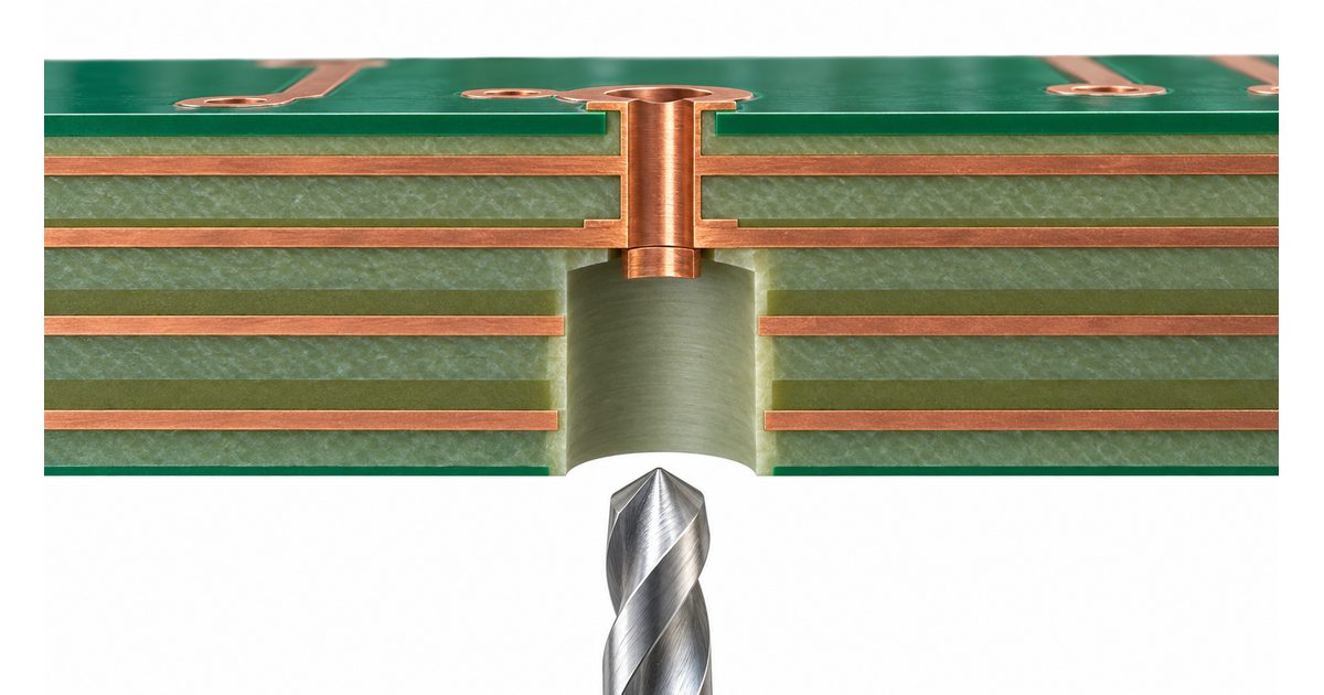
Table of Conent
Table of Conent
PCB backdrilling removes unwanted conductive barrel from a plated through-hole while preserving the part needed for the signal connection. It can help a high-speed channel when a via leaves an electrically significant unused stub. The design challenge is to remove enough copper to satisfy the electrical requirement without drilling into a connection that must remain.
A successful release therefore needs more than a note saying “backdrill critical vias.” The designer and fabricator must agree on the affected holes, entry side, retained connection, residual stub requirement, clearance, and evidence of the finished result. This guide explains that handoff for engineers and buyers preparing a multilayer PCB quotation.
Identify the unused barrel before choosing the process
A through-via can connect an outer layer to an internal routing layer while its plated barrel continues beyond that connection. The unused extension forms a stub. Its effect depends on the complete channel, including the transition geometry, material, signal spectrum, and surrounding reference structures. A layer count or data rate alone does not establish whether backdrilling is needed.
Texas Instruments discusses via discontinuities and backdrilled stubs in its High-Speed Interface Layout Guidelines. Treat recommendations in an application document within their stated context; do not turn a device-oriented guideline into a universal residual-stub specification for every design.
Start with the channel requirements and the actual routing transitions. Identify which barrel segments carry the intended signal and which extend beyond the last required connection. Review the channel model or the applicable device and interface guidance before adding a fabrication operation. Backdrilling should solve an identified problem, not simply make a multilayer drawing appear more advanced.
Distinguish backdrilling from a blind-via construction
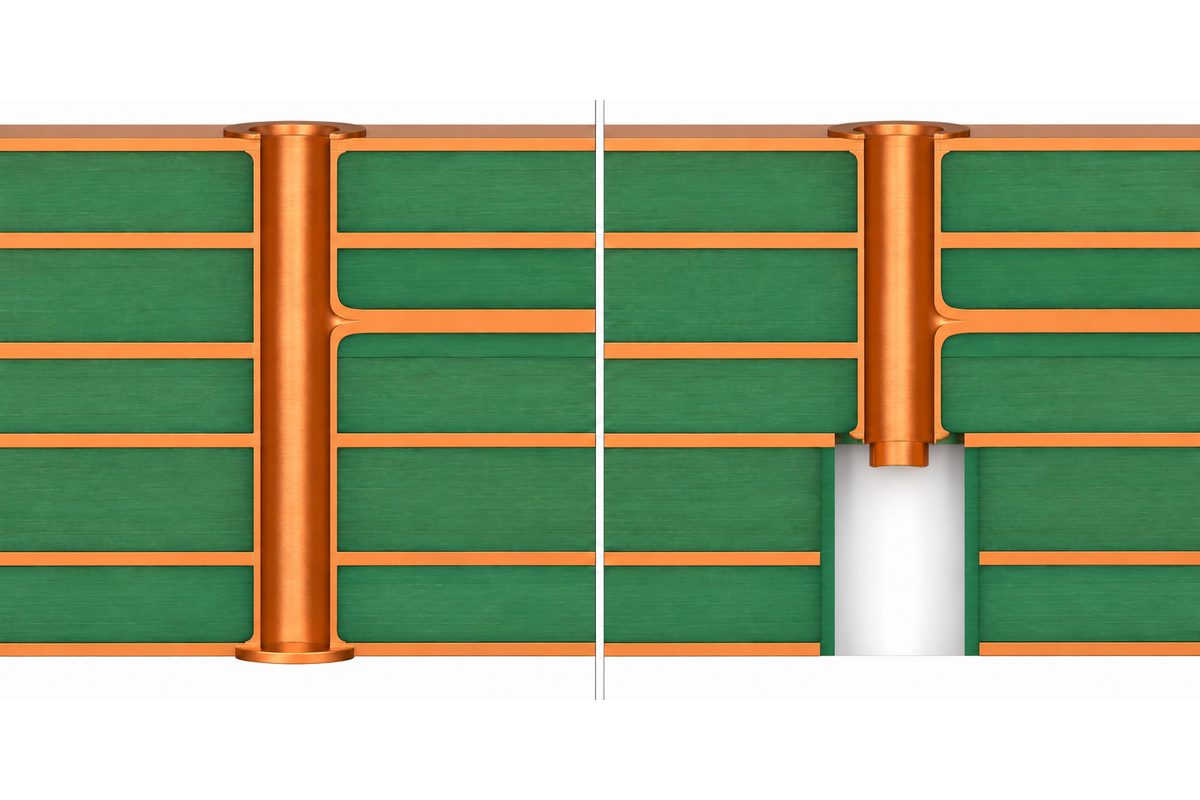
Conventional backdrilling starts with a plated hole and removes an unwanted section using a larger, controlled-depth drill. The retained section stays conductive. The enlarged section is not intended to become another plated interconnection. Specify any additional hole treatment separately rather than assuming it is included in the word “backdrill.”
A blind or buried via can avoid a similar unwanted extension through a different interconnection construction. That does not make the alternatives interchangeable in cost, layout, or fabrication planning. Review the board architecture and supplier proposal before selecting the process. If a simpler layer transition avoids the stub without creating another problem, include that option in the design review.
The multilayer PCB design-to-production guide provides the broader stackup context. For backdrilling, the important additional question is which copper must remain connected after the removal operation, not merely how many layers the board contains.
Map the entry side and every required connection
Create an explicit hole list or a controlled design selection for each backdrill operation. For every affected hole, identify the entry surface and the connection layer nearest the material being removed. A bottom-entry operation and a top-entry operation can have different protected connections even when they share the same XY location.
Use layer names that match the released copper files and stackup. If the fabrication drawing labels the top surface L1, do not describe the same surface as L12 in a separate drill note. An unambiguous orientation reference is especially important when a fabricator views bottom-side data in a different display orientation.
Check all connections to the affected barrel, not only the trace visible in the active CAD view. A hole may serve more than one layer or have a component-related purpose that a net-based selection misses. Do not backdrill a component hole simply because it shares a net class with ordinary routing vias. Confirm the permitted retained barrel and mechanical interface for that particular feature.
Define the residual stub separately from nominal drill depth
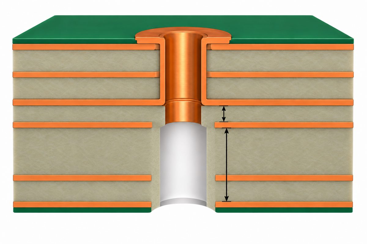
The residual stub is the unwanted conductive length left beyond the last required connection. Nominal drill depth describes a machining target from an entry reference. These are related quantities, but they are not the same acceptance criterion. A depth value without a stated stackup and protected connection can be interpreted incorrectly.
Agree on the measurement reference and whether a limit describes conductive copper remaining after processing. Clarify how the drill tip geometry and the transition between the original hole and enlarged cavity are treated. A schematic drawing should not substitute for a defined inspection interpretation.
The tolerance review must account for where the protected layer actually lies and where the backdrill operation can end. Ask the fabricator to propose a feasible process window that leaves the required connection intact while meeting the electrical limit. If the electrical requirement and manufacturing window conflict, resolve that conflict before issuing purchase approval.
The PCB thickness and tolerance guide explains why a nominal overall dimension is not the complete mechanical requirement. In a backdrill design, the relevant inner-layer positions and their relationship to the drilling reference also need to be reviewed.
Reserve clearance for the enlarged operation
The backdrill tool is larger than the original hole so it can remove the unwanted copper barrel. Review nearby traces, copper features, and adjacent holes against the proposed operation. The clearance check must use the backdrill envelope and the applicable positional allowances, not only the original plated-hole geometry.
Inspect each layer that the tool traverses. A safe distance on the entry surface does not prove clearance on an internal layer. Include plane openings and other copper in the review, and keep required signal and reference features outside the removal region. Avoid introducing a new transition problem while trying to remove a stub.
Ask how the supplier defines drill diameter, positional tolerance, and clearance in its proposal. Do not copy an oversize value from another supplier’s example and assume the resulting design is manufacturable. The larger operation can also affect placement near board features, so perform this review before the layout becomes difficult to change.
Keep CAD definitions and exported files consistent
Altium’s controlled-depth drilling documentation describes backdrill definitions, targeted holes, and oversize settings. It also explains that its drill-depth calculation depends on the defined layers. The practical release lesson is to verify the resulting output against the intended retained connection instead of relying solely on the presence of a CAD rule.
Check the exported drill files, drawing, and stackup together. Confirm the coordinate origin, units, tool definitions, and operation identity. A filename that distinguishes top-entry and bottom-entry data helps, but the drawing must still explain the operation. File naming cannot repair contradictory layer or depth requirements.
Preview the release in a manufacturing-data viewer when possible. Spot-check several holes from each operation and confirm that no unintended holes appear in the backdrill selection. Preserve the ordinary plated-hole data as well as the separate removal operation. The fabricator needs to understand both stages rather than infer the starting hole from an isolated backdrill file.
Preparing a high-speed prototype? Send the stackup, copper and drill data, backdrill operation map, quantity, and residual-stub requirement through the PCB engineering and quotation request. Ask for a review of the proposed process window and any file ambiguities before the order scope is finalized.
Use a fabrication package with clear ownership
A useful backdrill package includes the released board revision, controlled stackup, affected-hole data, entry side, protected connection, residual-stub requirement, and supplier-confirmed clearance assumptions. Identify the approved document if a requirement is specified outside the drawing. Avoid leaving an essential limit only in an email that production may not receive.
State whether a depth is a proposed design value or a supplier-approved manufacturing value. If the fabricator calculates the operation from the stackup, document who approves that calculation and which design requirement it must satisfy. This prevents purchasing from accepting a tooling interpretation that the design owner has never reviewed.
Compare the wider design with the PCB manufacturing capabilities, then request project-specific confirmation for backdrilling. A general capability page is not evidence that a particular residual stub, drill span, or tolerance combination has been accepted for your board.
Agree on verification before the boards are built
Define the evidence needed to accept the removal operation. Possible project requirements include dimensional evaluation of representative sections, confirmation that required connections remain intact, and electrical or channel-related checks. Select methods and sampling with the supplier rather than assuming that every order includes the same inspection scope.
Continuity testing can confirm the connections covered by the test, but it does not by itself measure the residual stub. Likewise, an image of a drilled cavity is not a channel-performance test. Match each requirement to evidence capable of answering that question, and specify which records should accompany the shipment.
For section-based evaluation, agree on sample locations, orientation, measurement interpretation, and reporting. A sample must be relevant to the operation being evaluated. If several entry sides or protected layers are involved, discuss coverage for those differences rather than treating one convenient section as proof of every hole on the board.

Compare quotations on the same backdrill scope
Ask each supplier to quote the same affected-hole population and the same controlled stackup. Separate questions about operation count, entry sides, setup, inspection, and required reports. A quote based on a different residual-stub interpretation is not directly comparable even if the bare-board dimensions match.
If a supplier proposes a larger remaining stub or a different construction, send the proposal back to the electrical design owner. The purchasing team should not approve an electrical requirement change solely to close a price or schedule difference. Record the decision and update the release documents when a change is accepted.
When the scope is still open, include the unresolved depth, clearance, and inspection questions in the backdrill PCB quotation request. Supply the current files and identify the items that need engineering confirmation so the quotation can distinguish agreed work from remaining assumptions.
Control changes after the prototype review
As a hypothetical example, moving a signal transition to another internal layer can change the unused barrel length while leaving the hole’s XY location unchanged. The old backdrill file may still align perfectly with the new artwork but protect the wrong connection. Review the operation whenever routing or stackup changes affect the intended interface.
Repeat the review for material or construction substitutions that alter relevant layer positions, and for changes to the selected drill population. Maintain one release revision across the drawing, stackup, and machine data. Do not mix an approved prototype drawing with a later drill file just because their filenames look familiar.
Conclusion
PCB backdrilling is a targeted removal process with an electrical goal and a manufacturing tolerance window. Identify the unused barrel, protect the required connections, reserve clearance for the enlarged drill, and release consistent operation data. Agree on residual-stub interpretation and acceptance evidence before fabrication begins.
Ready to review the build? Submit the released stackup, Gerber or equivalent manufacturing data, ordinary and backdrill files, board quantity, schedule, and inspection requirements through the online PCB RFQ form for engineering and quotation review. Highlight the retained layers and residual-stub limits so the proposed scope can be evaluated accurately.
Latest Blog
Contact Info
Phone: +86-755-82882936
Email: [email protected]
WhatsApp: +86-13570802455
Wechat: +86-13570802455
Address: 2nd floor,D Bldg.,Electric Link Technology Bldg.,Gongming,Guangming New Dist.,518106 Shenzhen, China