
PCB Impedance Testing: Coupons, TDR Windows, and Report Review
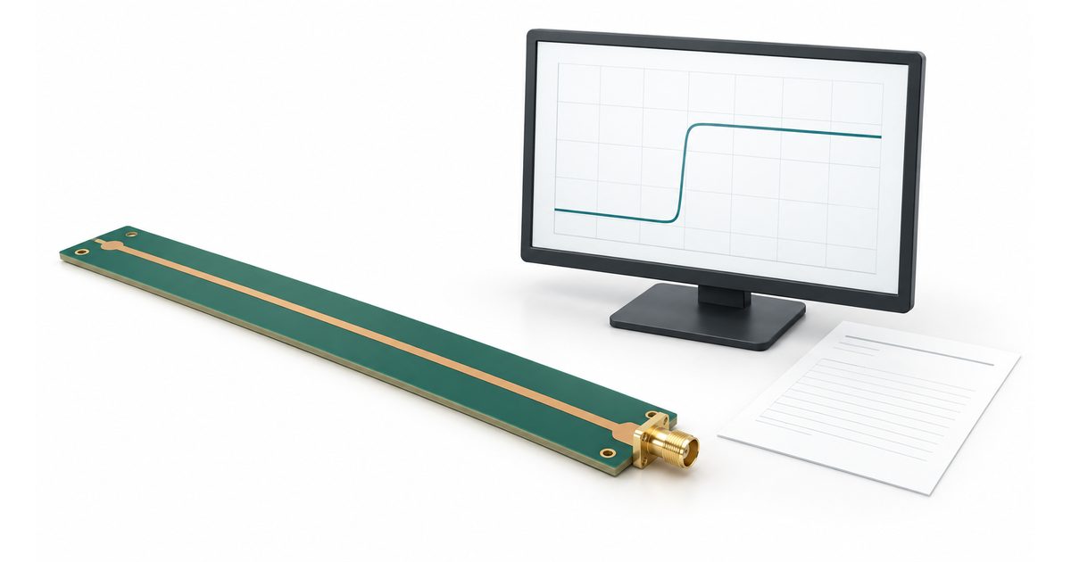
Table of Conent
Table of Conent
PCB impedance testing can confirm a defined transmission-line requirement, but an impedance number is only meaningful when it is tied to the right specimen and measurement conditions. A report should tell the buyer which structure was measured, how it represents the ordered board, which part of the waveform was evaluated, and what acceptance rule was applied.
This guide focuses on reviewing time-domain reflectometry (TDR) evidence for manufacturing. It does not replace a signal-integrity design review, prescribe a universal coupon geometry, or claim that a coupon result validates every interconnect in a finished product. The objective is to make the drawing, specimen, test method, and report agree.
Identify the impedance requirement before testing
State the target, tolerance, signal layer, reference structure, and whether the requirement is single-ended or differential. Include a controlled stackup and identify the relevant trace geometry. A note that simply says “controlled impedance” leaves the laboratory and fabricator without a complete comparison basis.
Do not mix a single-ended result with a differential target. Ask the supplier to identify the measurement configuration and the structure it evaluates. Do not assume that a differential value can always be obtained by doubling a single-ended result.
The official IPC-TM-650 Method 2.5.5.7A describes deriving characteristic impedance from TDR observations. It covers measurement-system and specimen limitations, including differences in accuracy and repeatability between approaches. Specify the applicable method and agree the acceptance requirement separately.
Keep the target and its tolerance under drawing revision control. If construction changes are proposed, review their effect on the complete stackup rather than approving an isolated trace-width edit without context.
Link the coupon to the ordered construction
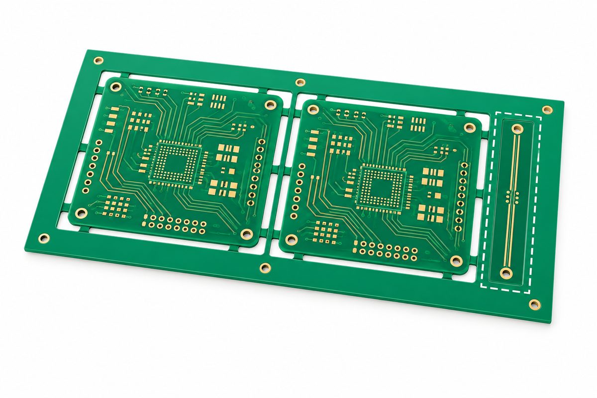
Identify whether the specimen is a production-panel coupon, a designated structure on the board, or another agreed test vehicle. Keep the specimen number connected to the board revision and production lot. A coupon without a clear relationship to the shipment is weak acceptance evidence.
The cited IPC method includes representative board structures and coupons among its specimen examples. Ask how the selected specimen represents the controlled layers and construction. Do not infer representation from the coupon’s green color, layer count, or nominal label alone.
For a multilayer board, list the impedance requirements to be evaluated rather than assuming one coupon result covers every signal layer. If different structures have different requirements, keep their results separately identified in the report.
Our PCB thickness selection guide provides context for documenting finished construction and stackup decisions. Overall board thickness does not replace the layer-specific geometry required for an impedance review.
Send your PCB files, controlled stackup, impedance table, and requested coupon evidence for a manufacturing quote review. Identify single-ended and differential requirements so the proposed construction and verification scope can be discussed before release.
Read the measurement window with the result
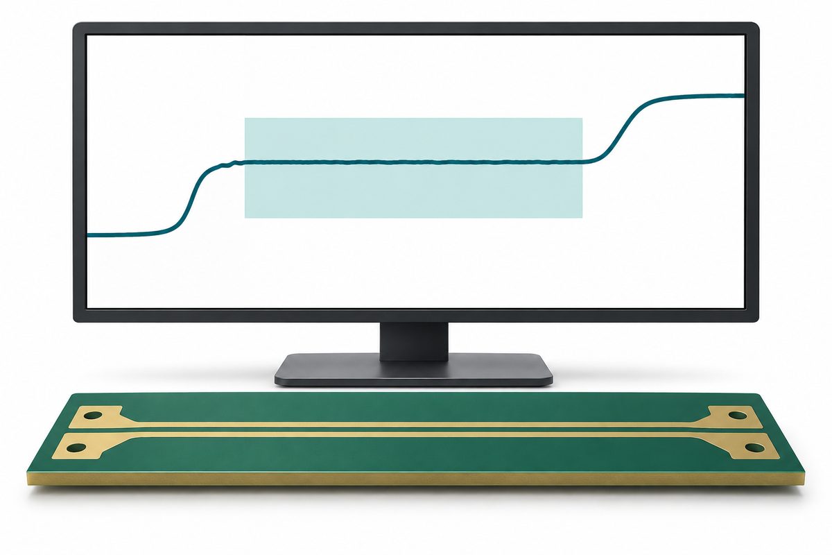
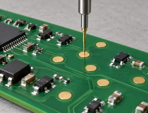
A TDR connection includes the measurement system and its transition into the specimen. A reported value should therefore identify the evaluated interval rather than presenting only a cropped curve or a number without context.
Polar Instruments’ short-trace measurement note explains why launch and end effects can leave limited usable measurement length. It also cautions that a commonly suggested percentage window may not be appropriate for a short trace. Use the applicable method and specimen review, not a universal screenshot template.
Request the waveform with its units, selected region, and reported statistic. If an average is used, state how it relates to the acceptance rule. An acceptable average does not automatically establish compliance with a separately specified requirement for variation within the evaluated region.
Do not move the window after seeing an unfavorable result merely to obtain a pass. A revised window needs a technical explanation and controlled approval. Preserve the original result and show why the change is appropriate for the specimen and method.
When there is no clearly suitable interval, report that limitation and discuss another specimen or measurement approach. A short coupon should not be declared acceptable just because a very narrow segment happens to cross the nominal target.
Review setup and calibration before comparing laboratories
Ask for the instrument and connection configuration, relevant calibration information, rise-time or filtering settings where applicable, specimen orientation, and the calculation approach. Two visually similar curves do not necessarily represent comparable setups.
Polar’s measurement-error guidance discusses calibration, connection wear, drift, and the influence of handling and nearby surfaces. These are reasons to document the setup, not instructions to dismiss every out-of-tolerance measurement as an instrument problem.
Keep the agreed setup consistent during a production comparison. Record any equipment or method change as a change in the evidence chain. If a supplier and customer disagree, compare the same specimen and configuration where practical before deciding that the construction is wrong.
Do not use an apparently precise display value as proof of equivalent measurement accuracy. Ask how measurement uncertainty and repeatability are considered in the project’s decision rule, especially when a result is close to the limit.
If the laboratory proposes an alternative method, request its applicability and the reporting changes before accepting it. A method name alone is not a substitute for a reproducible evaluation.
Apply the actual acceptance rule
For illustration only, a hypothetical 50-ohm target with an agreed plus-or-minus 10% tolerance has numerical limits of 45 and 55 ohms. These are example requirements, not an AssyPCB capability claim or a universal industry acceptance limit.
The arithmetic is the easy part. The order must also establish what quantity is compared with those limits, which specimen is evaluated, how uncertainty is handled, and how exceptions are approved. Avoid treating every possible waveform value as the controlling result unless that is actually the agreed requirement.
Record individual structure results rather than only a lot average. Keep the nominal target, limits, measured quantity, and disposition on the same report line. This makes a mismatched target or a copied tolerance easier to identify during incoming review.
Do not use a pass label from a prior revision when a new stackup or geometry has been released. The evidence should identify the construction it actually represents.
Keep impedance evidence separate from other tests
The bare-board electrical testing guide addresses connectivity, test-reference integrity, and traceable results. Continuity and isolation evidence does not establish the characteristic impedance of a transmission line. Likewise, a coupon impedance result does not replace the required connectivity test.
Do not present an impedance coupon report as a complete end-to-end signal-integrity or product qualification result. The actual interconnect may include connectors, vias, branches, and other features outside the evaluated uniform structure. Identify any additional analysis or testing required by the project.
Keep the report’s conclusion proportional to its scope: a specified specimen met a specified requirement under the stated method. Broader claims need their own evidence.
Request a decision-ready report

A useful report identifies the board and stackup revision, lot or panel, specimen, evaluated layer and structure, measurement configuration, target and limits, waveform region, result, method, and exceptions. Images and numerical tables should share the same specimen identifiers.
Ask which records will be retained and whether raw traces are included or available. Confirm the sampling plan and how coupon results relate to shipped boards. Do not infer that every board or every route was directly measured from a general statement that impedance was tested.
If a retest occurs, retain the original result and record why the retest was needed. Identify changes to connection, setup, specimen, or processing. A later pass without that explanation does not resolve the evidence gap.
Request a project review with your impedance requirements and required report fields. Include sampling, trace retention, and any customer-controlled acceptance procedure so testing and documentation assumptions can be confirmed.
Example: a matching number from the wrong structure
Consider a hypothetical shipment whose report shows a result near the requested target, but the coupon identifier refers to a different signal layer from the drawing. The number alone cannot establish compliance for the requested structure. The buyer first checks the specimen-to-layer mapping and the stackup revision, then asks for the evidence corresponding to the actual requirement. If that evidence is missing, the report remains incomplete even though the displayed value looks favorable. This example is not an AssyPCB production case; it illustrates why specimen identity belongs beside the measured result.
Close the purchase requirement before release
Provide fabrication files, stackup, layer-specific impedance requirements, approved geometry changes, coupon expectations, sampling, and report format. Identify who approves deviations and how ambiguous results are handled. Ask the supplier to resolve missing information before the order becomes a production problem.
The controlled-impedance service page is a starting point for project discussions. Confirm the requested construction, test method, and acceptance arrangement rather than assuming a general service page establishes every custom tolerance.
Submit your PCB files, impedance table, and verification requirements for a project-specific quote. Traceable coupons, a defensible measurement region, and a clearly defined report make impedance evidence more useful to both engineering and purchasing.
Latest Blog

Contact Info
Phone: +86-755-82882936
Email: [email protected]
WhatsApp: +86-13570802455
Wechat: +86-13570802455
Address: 2nd floor,D Bldg.,Electric Link Technology Bldg.,Gongming,Guangming New Dist.,518106 Shenzhen, China