
Patient Monitor PCB Design: Link Each Channel to Verification Evidence
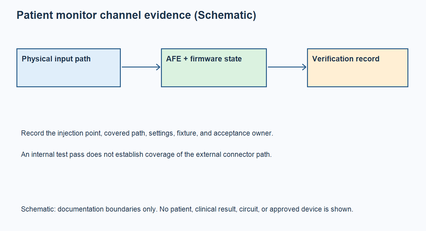
Table of Conent
Table of Conent
Patient monitor PCB design should connect every measurement channel to a defined signal path, controlled firmware settings, and an approved verification record. Before an assembly order is released, identify where a bench stimulus enters, which circuitry it exercises, what the result demonstrates, and who owns the remaining device-level evaluation. An electrocardiogram (ECG) front-end self-test, a plausible peripheral oxygen saturation (SpO2) display, or a clean inspection image cannot independently establish complete patient-monitor safety or measurement performance.
For an original equipment manufacturer (OEM) buying a populated board, the useful handoff is a channel map plus a test-coverage matrix tied to the actual board revision, programmed configuration, fixture, and acceptance criteria. This guide develops that manufacturing handoff using ECG and optical front-end examples. It does not prescribe patient testing, universal safety spacings, clinical accuracy limits, or a complete compliance program. Applicable requirements and release decisions remain with the responsible device team and qualified reviewers.
Sources reviewed October 22, 2026; component examples retain their stated data-sheet revisions.
Define each measurement channel and its owner
Map the complete measurement chain before assigning PCB responsibilities. The Microchip patient-monitor architecture overview describes equipment that measures, records, distributes, and displays combinations of physiological values. That equipment function is broader than the populated board being purchased.
For each channel, identify the sensor or external module, connector, protection and filtering, analog front end (AFE), conversion, processing, display or data output, and relevant power source. Mark which items are on this PCB, elsewhere in the enclosure, or supplied as accessories. Include the board variant and enabled firmware functions so an unpopulated option is not mistaken for a failed channel.
| Channel | Define the board boundary | Record in the approved bench procedure | Keep separate |
|---|---|---|---|
| ECG | Connector, input network, AFE, conversion and digital output | Injection point, channel selection, gain, filtering and observed response | Complete equipment safety and clinical performance |
| Optical sensing | Probe interface, LED drive, photodiode receive path and processing interface | Probe or simulator identity, timing, gain, phase data and processing version | System-level SpO2 accuracy evaluation |
| Non-invasive blood pressure | Pressure interface and any on-board control or external-module connection | Approved pneumatic or module simulation setup and covered functions | Whole-system pressure and measurement validation |
| Temperature | Probe or sensor interface, conversion and reported value | Approved simulator or reference, channel configuration and result units | Probe-system performance outside the tested scope |
The matrix is a scoping example, not a mandatory test list. A board that communicates with a separate qualified measurement module needs a different procedure from one containing the complete analog channel. Name the owner of each excluded function before comparing assembly quotations.
Map the safety boundary before placing test access
Define patient-connected, internal power, communication, enclosure, and service interfaces before adding fixture contacts or debug access. Their relationships belong in the safety review; the layout team should not decide them from a generic spacing table.
The IEC 80601-2-49:2018+AMD1:2024 public scope addresses basic safety and essential performance of multifunction patient monitors. It also distinguishes that equipment scope from requirements for individual physiological monitoring units. The public catalog establishes this boundary, but it is not the complete standard or a product-specific applicability assessment.
Have the responsible reviewer define the applicable standards, editions, operating environments, protection requirements, and acceptance evidence. Show the proposed power supply, patient accessories, external ports, and manufacturing or service connections in the same interface map. Ask whether a fixture, grounded instrument, programming connection, or external supply changes the reviewed arrangement.
Translate approved constraints into controlled drawings and fixture requirements. Keep safety-related construction details, component restrictions, inspection points, and authorized tests visible to the manufacturer. Do not treat an isolated component, a PCB workmanship class, or a successful functional test as certification of the assembled monitor.
Verify the external ECG path as well as the AFE
State the stimulus entry point whenever an ECG test is specified. An internally generated AFE test signal can support subsystem checks while leaving the external connector and input network unexercised.
For example, the ADS129x data sheet, Revision K, describes an input multiplexer and internal test signals; it explicitly says that the test-signal feature is not intended for compliance testing. Use that feature within its documented purpose. A passing result does not justify declaring every upstream connection, filter, protection element, or accessory correct.
Separate an internal subsystem check from an approved external-path check in the coverage matrix. For each, record the selected channel, stimulus source, injection node, configuration, observed output, and excluded circuitry. If the firmware changes gain or filters between operating modes, identify the configuration actually exercised rather than saving only a pass flag.
During layout review, follow the analog return paths, reference connections, decoupling, and digital routing around the selected AFE. Check whether proposed test access changes a sensitive input route or the reviewed interface boundary. Carry any required assembly and cleaning controls into the released drawings rather than leaving them in a bench notebook.
When the production test boundary is still unclear, share the channel map and unresolved test boundaries with the BOM, interface drawings, quantity, and approved bench-test requirements. OrinewPCB can review the manufacturing inquiry and identify missing fixture, programming, inspection, or test inputs. Required medical-project qualifications and the specific scope of any proposed testing must be confirmed separately.
Check optical timing under shared operating loads
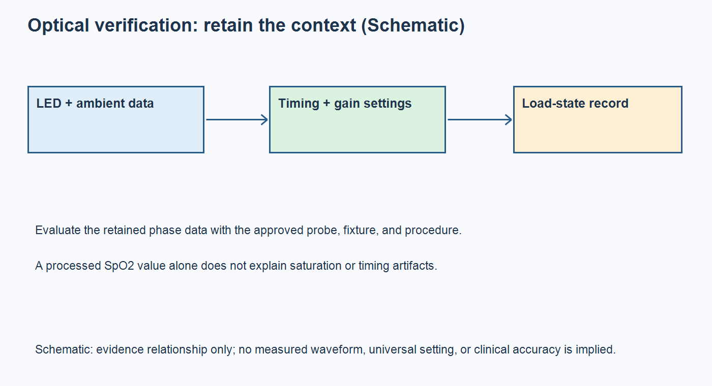
Evaluate optical channel data together with its timing, gain, probe, and operating-state records. A processed oxygen-saturation number alone does not explain how the electronics behaved.
As a device-specific example, the AFE4404 data sheet, Revision D, describes LED and ambient sampling phases. Its application discussion explains that timing differences and saturation can limit ambient-light cancellation. That dependency makes configuration and raw phase evidence useful when investigating an optical channel; it does not supply a universal production setting or establish clinical SpO2 accuracy.
For an approved bench evaluation, retain the probe or simulator identity, register configuration, LED and ambient phase data, processing version, and relevant conditions. Distinguish an electrical stimulus applied to the receiver path from an optical setup that exercises the emitter, detector, and their physical arrangement. The two approaches cover different parts of the chain.
Include approved combinations of shared loads in the engineering verification plan: display operation, communication activity, power-source changes, or an on-board pump if one exists. Record the operating mode beside the channel result. A comparison taken with different firmware, probe, or load conditions cannot isolate the board change confidently.
Use the findings to define which checks belong in the released manufacturing procedure and which remain engineering evaluations. Do not add an arbitrary load sequence to every unit merely because it produced an interesting bench waveform. Acceptance criteria, equipment capability, repeatability, and cycle time need an agreed basis.
Separate production checks from device validation
Give every inspection or test a bounded claim. Production evidence should say what was checked on the delivered board, while complete-device safety, performance, and regulatory evaluations retain their own owners.
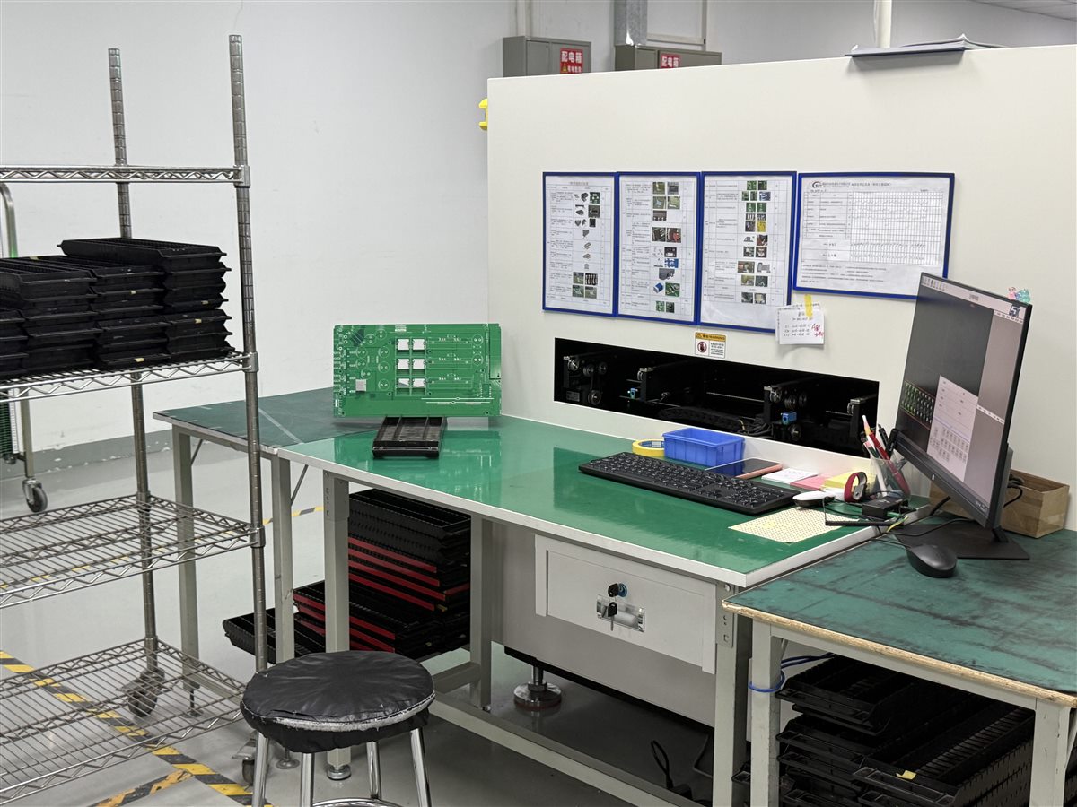
For example, bare-board electrical test coverage concerns the manufactured conductive networks before assembly. Assembly inspection and a programmed functional procedure add other evidence, but none of those labels alone describes the complete measurement chain. Save the method and revision instead of compressing unlike checks into “fully tested.”
| Proposed change | Coverage question | Evidence to review | Owner to name |
|---|---|---|---|
| Input-network or AFE alternate | Does the approved external-path check still address the changed behavior? | Part comparison, affected circuit and channel results | Hardware and quality |
| Firmware or register settings | Were the released gain, filtering, timing and output functions exercised? | Program identity, configuration and raw/processed results | Firmware and verification |
| Optical probe or accessory | Does the old fixture represent the new physical signal path? | Accessory identity, fixture scope and system evaluation needs | System engineering |
| Power, display or communication load | Are relevant concurrent operating conditions still represented? | Load-state record, channel behavior and applicable safety-review disposition | Hardware and safety reviewer |
Preserve initial failure evidence when a unit later passes a retest. Record whether the intervening action changed the board, firmware, fixture contact, accessory, or procedure. If a result is invalidated, retain the reason and authorized disposition. Otherwise, a final pass can conceal which configuration produced the original failure.
This proposed change-review matrix supports traceable engineering decisions. It is not a substitute for the device team’s risk management or validation plan. Bench manufacturing checks described here use approved fixtures and simulators, not a patient as the test source.
Freeze channel records before repeat builds
Release the board, firmware, fixture, limits, and record format as one consistent manufacturing baseline. A repeat order should identify that baseline explicitly instead of assuming the previous test program still applies.
Use controlled BOM alternate approval to keep sourcing changes from silently altering a measurement channel. Preserve the exact populated variant, approved parts, programming identity, fixture and procedure revisions, equipment status, results, retests, and release disposition at the agreed traceability level.
The turnkey PCB assembly scope can help organize fabrication, sourcing, and assembly responsibilities. Project acceptance still depends on the actual requirements, required qualifications, and agreed exclusions; no general service description establishes medical-device eligibility.
A useful patient-monitor PCB handoff therefore connects each physical channel to its configuration, covered test path, and retained evidence. Close missing ownership and coverage questions before production release, and reopen the affected review after a material, firmware, accessory, or interface change.
For a manufacturing-scope assessment, provide the released fabrication and assembly files with the BOM, placement data, drawings, firmware and approved test procedures, quantities, traceability and qualification requirements, and delivery expectations. OrinewPCB can review fabrication, sourcing, assembly, and proposed test responsibilities together, with device-level safety and performance decisions retained by their designated owners.
Latest Blog
Contact Info
Phone: +86-755-82882936
Email: [email protected]
WhatsApp: +86-13570802455
Wechat: +86-13570802455
Address: 2nd floor,D Bldg.,Electric Link Technology Bldg.,Gongming,Guangming New Dist.,518106 Shenzhen, China