
Lead-Free vs Leaded Solder: Qualify the Whole Assembly
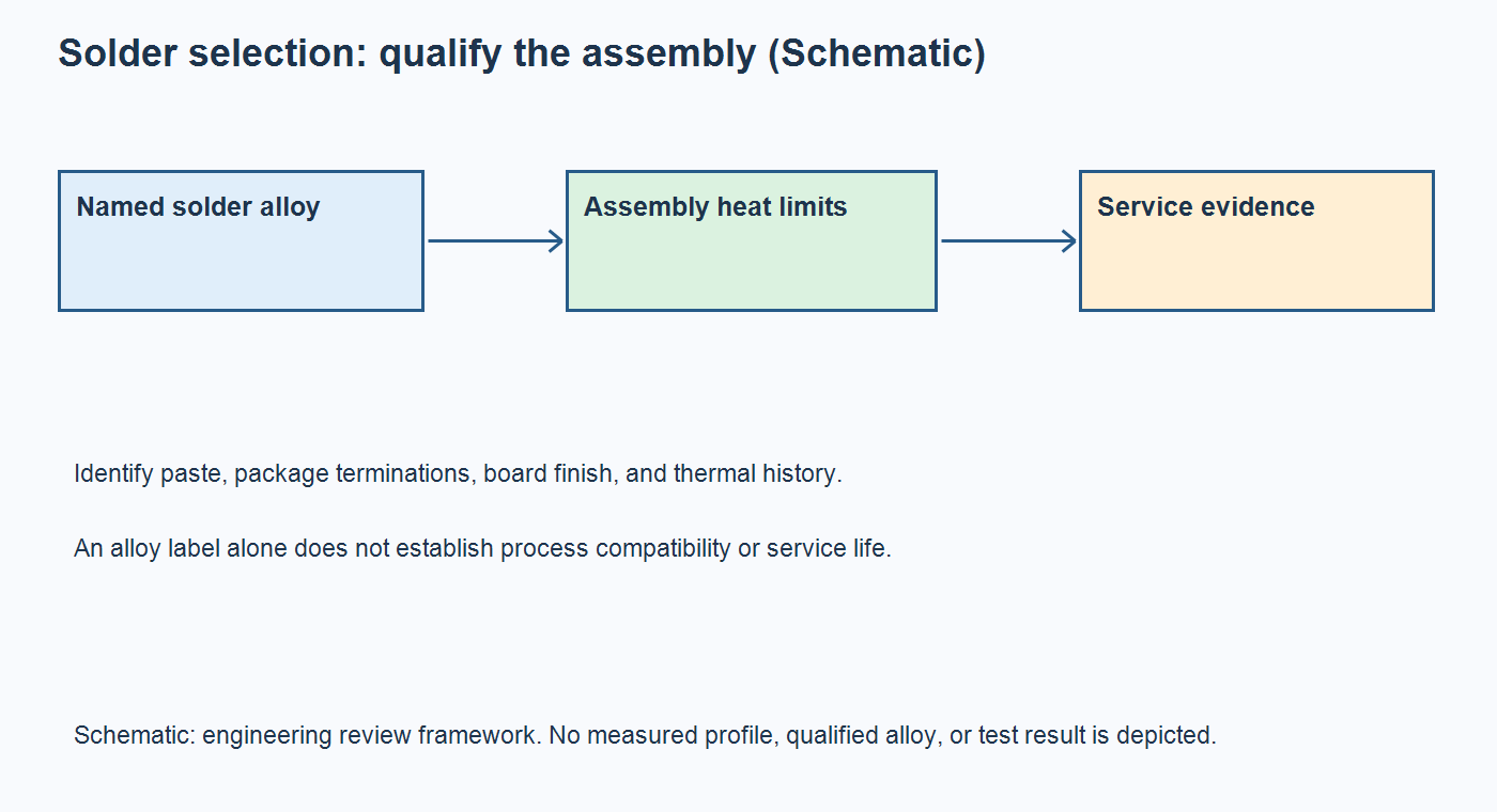
Table of Conent
Table of Conent
Choose lead-free or leaded solder by qualifying the complete assembly, including its component terminations, board finish, thermal exposure, and service requirements. Sn63Pb37 and SAC305 are specific alloys; “lead-free” covers several different systems. A lower melting temperature can reduce the heat needed to form a joint, but it does not establish a safe oven recipe or longer service life. Likewise, changing only the paste does not define the composition of a joint that also contains a BGA solder ball.
For an OEM or assembly buyer, the useful comparison is a controlled release decision: identify the exact materials, find a compatible time-temperature process, and agree what evidence supports the intended environment. Keep product compliance requirements with the responsible product owner. This guide addresses assembly engineering and procurement, with source checks dated October 22, 2026; it does not determine regulatory exemptions or authorize an alloy for a particular safety-critical product.
Compare named alloys rather than broad labels
Compare exact alloy designations before discussing temperature or reliability. Tin-lead solders do not all melt at one temperature, and lead-free solders are not interchangeable.
The Kester alloy chart lists the following values. SAC305 denotes a nominal tin-silver-copper composition of 96.5/3.0/0.5 by weight. These material values are reference points for process development, not oven setpoints.
| Alloy | Listed melting range | Release implication |
|---|---|---|
| Sn63Pb37 | 183 °C | Identify the exact paste and package limits before developing the profile. |
| Sn60Pb40 | 183–190 °C | Do not substitute its melting behavior for the eutectic Sn63Pb37 reference. |
| SAC305, Sn96.5Ag3Cu0.5 | 217–220 °C | Review the higher melting range against the populated assembly’s permitted exposure. |
A purchasing description should include the paste manufacturer, product code, alloy, powder specification where relevant, flux system, and approved alternatives. “Lead-free paste” leaves too much unresolved for a repeatable build. Record the material actually issued to production, including its lot and handling history.
Keep business requirements explicit. A customer may require a particular alloy, restricted-material declaration, or approved manufacturing route. Engineering should resolve those requirements before procurement compares apparently equivalent quotations. A material label alone is insufficient evidence for the compliance of the finished product.
Find a thermal window for the populated board
A usable reflow process must satisfy the solder system’s needs while respecting every relevant component and board limit. Melting temperature, measured joint temperature, package-body temperature, and oven-zone setting describe different things.
For example, Kester’s general SnPb profile shows a 210–230 °C peak, above the 183 °C reference for Sn63Pb37. That chart illustrates why melting and process peak differ; the actual paste documentation and assembly limits still govern.
TI’s nFBGA packaging guidance, revised May 2021, presents separate Pb-free and eutectic SnPb profiles and defines the illustrated reflow temperature at the package top. It also describes application-dependent profile changes. Do not transfer a package-top limit directly to an inaccessible solder joint, or treat one package example as a recipe for the whole BOM.
Build a requirements sheet containing the paste’s process guidance, each sensitive part’s allowed exposure, board construction restrictions, moisture-handling requirements, and expected number of thermal passes. Include both sides of a double-sided build and the planned repair sequence. An acceptable first pass does not automatically clear later heating.
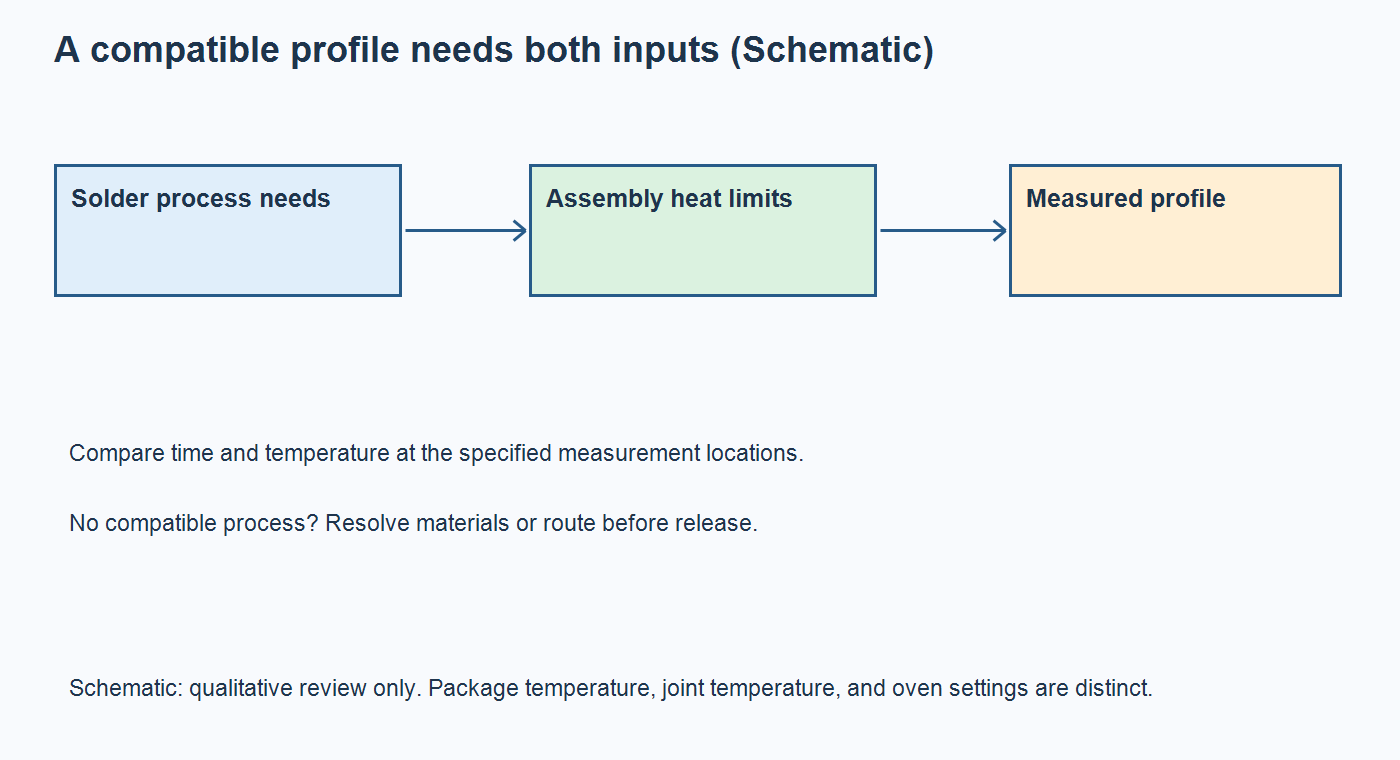
Define the review outcome before the trial: accepted within documented conditions, rejected, or pending a named question. Retain the temperature traces alongside the limits used to judge them. A screenshot without the measurement locations and assembly revision cannot resolve a later disagreement about whether the coldest joint or hottest component was represented.
Use thermocouple placement for mixed-mass assemblies to identify potentially slow-heating joints and vulnerable locations. Record the sensor attachment, populated revision, panel arrangement, loading, and conveyor conditions. If no compatible process exists, change the materials or assembly route rather than approving an average temperature that conceals a local violation.
Resolve package metallurgy before approving a substitute
Treat a change in solder paste, component finish, or BGA ball alloy as a joint-system change. The paste designation does not identify all the metal entering the finished connection.
Request the exact orderable component number and manufacturer’s termination or ball information. A procurement substitute with the same electrical function can introduce a different assembly assumption. When the ball alloy is unknown, keep that question open instead of inferring it from the package name or a distributor’s broad environmental label.
If an alloy migration is still being scoped, share the alloy change and component constraints with the proposed paste, BOM, drawing revision, quantities, and known thermal limits. The team can identify sourcing and assembly questions and define the profiling work needed before a production quotation is finalized.
| Proposed change | Evidence to obtain | Hold release when |
|---|---|---|
| Paste product or alloy | Current technical data, material identity, measured trial profile and inspection plan | Existing process evidence describes another formulation or alloy. |
| BGA or termination variant | Exact part number, ball or finish identity, supplier assembly guidance | Compatibility is assumed from electrical interchangeability. |
| Board surface finish | Released finish, storage history and planned thermal sequence | The finish change was omitted from the assembly review. |
| Rework route | Original and replacement metallurgy, residual material treatment, added exposure and verification | A repaired joint is treated as equivalent without an approved basis. |
Keep the surface finish and solder alloy separate
Specify the bare-board finish independently from the assembly solder. A finish protects the solderable copper before assembly and participates in the interface; it is not a complete description of the solder joint.
In particular, a HASL description needs to distinguish the specified finish chemistry. An ENIG or OSP drawing note does not determine whether production uses SnPb or SAC paste. Confirm pad geometry, finish condition, intended storage, assembly passes, and any repair exposure together. A finish change can require another wetting or process review even when the paste remains unchanged.
The official OrinewPCB explainer below compares ENIG, HASL, and OSP in terms of flatness, storage, and assembly requirements. It supports this finish-selection question; it is an AI-generated explainer, not a measured alloy-reliability comparison or factory qualification record.
Keep material identity connected to handling evidence. The solder paste storage and issue records help distinguish a formulation change from an uncontrolled container history. Review stencil, replenishment, repair-wire, and returned-material identification so a later investigation can reconstruct which materials reached each build. The required segregation method should follow the approved process; do not assume every supplier uses identical equipment arrangements.
Match reliability evidence to the service load
Neither “leaded is stronger” nor “lead-free is more reliable” is an adequate acceptance rule. Ask whether the evidence represents the actual package, joint construction, manufacturing history, and loads the product will experience.
NASA’s 2005 lead-free solder evidence summaries describe results that vary with package, thermal-cycling conditions, mixed assembly, and rework. These historical summaries explain why a universal ranking is inappropriate. They do not qualify a present-day alloy, product, or OrinewPCB process.
Separate manufacturing verification from service qualification. A profile and inspection record establish what happened during assembly and what was observed afterward. They do not establish fatigue life under the customer’s temperature cycles, resistance to a mechanical load, or performance after the intended storage period. Select the qualification conditions and acceptance criteria through the product’s engineering plan.
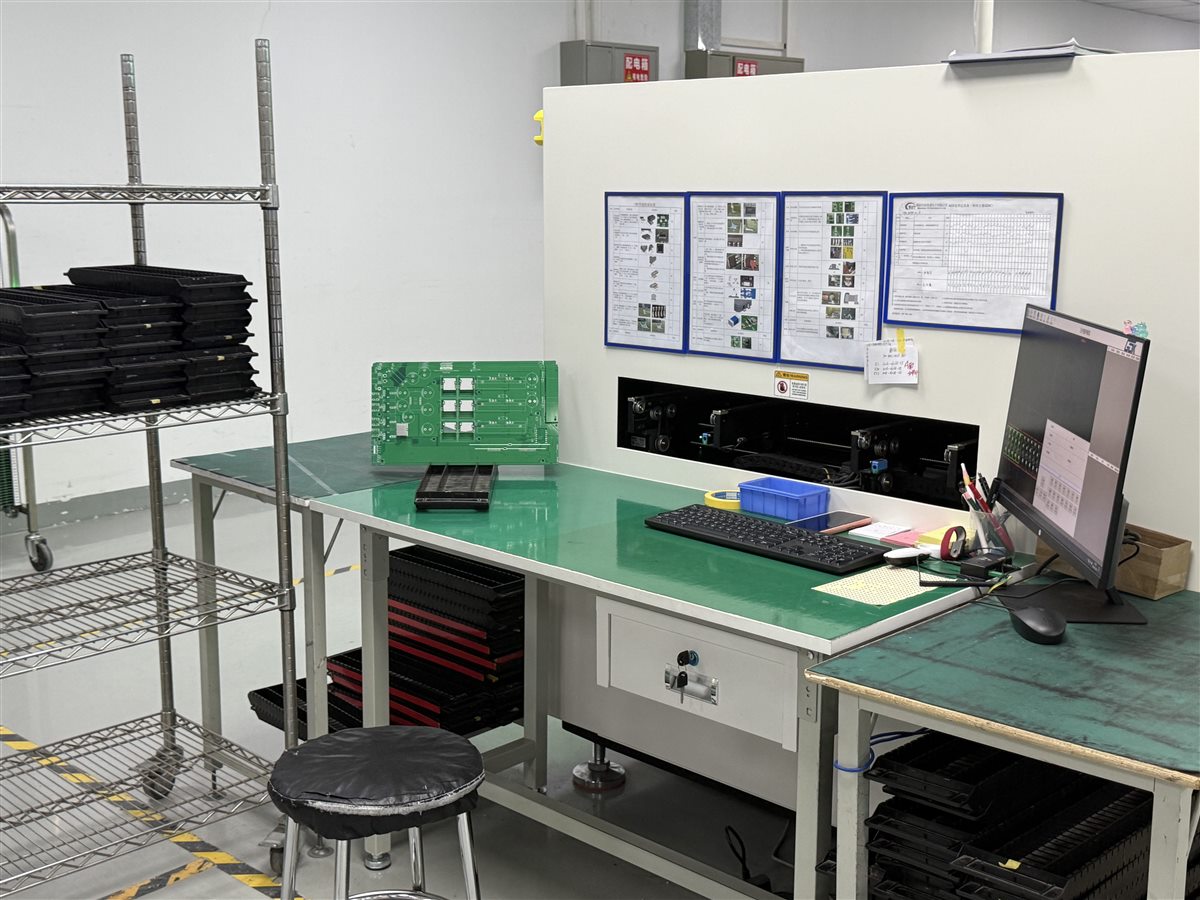
Ask the buyer and product engineer to distinguish a material change from a requirements change. If the target environment has also changed, an earlier pass may no longer answer the purchasing question even when manufacturing repeats the original recipe.
For a proposed comparison build, hold package identity, board layout, finish, and operating assumptions constant where practical. Document unavoidable differences instead of attributing every outcome to the alloy. Agree which joints are monitored, how a failure is defined, and who decides whether existing evidence transfers to a changed construction.
Release the alloy decision with the complete build package
Release one consistent manufacturing revision after the alloy, thermal process, and required acceptance evidence have been reconciled. A lower paste price or familiar alloy is useful only when the assembly route remains acceptable.
Keep the approved BOM, board finish, solder material, substitution rules, profiling record, inspection requirements, and repair disposition linked. Changes to a ball alloy, paste product, board construction, sensitive component, or number of heating passes should trigger an engineering applicability review. Procurement should retain the approved answers for repeat orders.
The turnkey PCB assembly scope connects fabrication, component sourcing, assembly, and testing. Confirm the particular alloy and verification requirements with OrinewPCB rather than interpreting a general service description as approval of a special process.
The practical choice is the solder system supported by the product requirements and assembly evidence. For a project ready to proceed, provide the released assembly package and alloy requirements with Gerber or ODB++ data, BOM, placement files, drawings, quantities, permitted substitutions, test requirements, and delivery needs. Those inputs allow the fabrication, sourcing, assembly, and requested test scope to be reviewed on the same basis.
Latest Blog
Contact Info
Phone: +86-755-82882936
Email: [email protected]
WhatsApp: +86-13570802455
Wechat: +86-13570802455
Address: 2nd floor,D Bldg.,Electric Link Technology Bldg.,Gongming,Guangming New Dist.,518106 Shenzhen, China