
Blister Packer PCB Field Failures: Preserve the Evidence
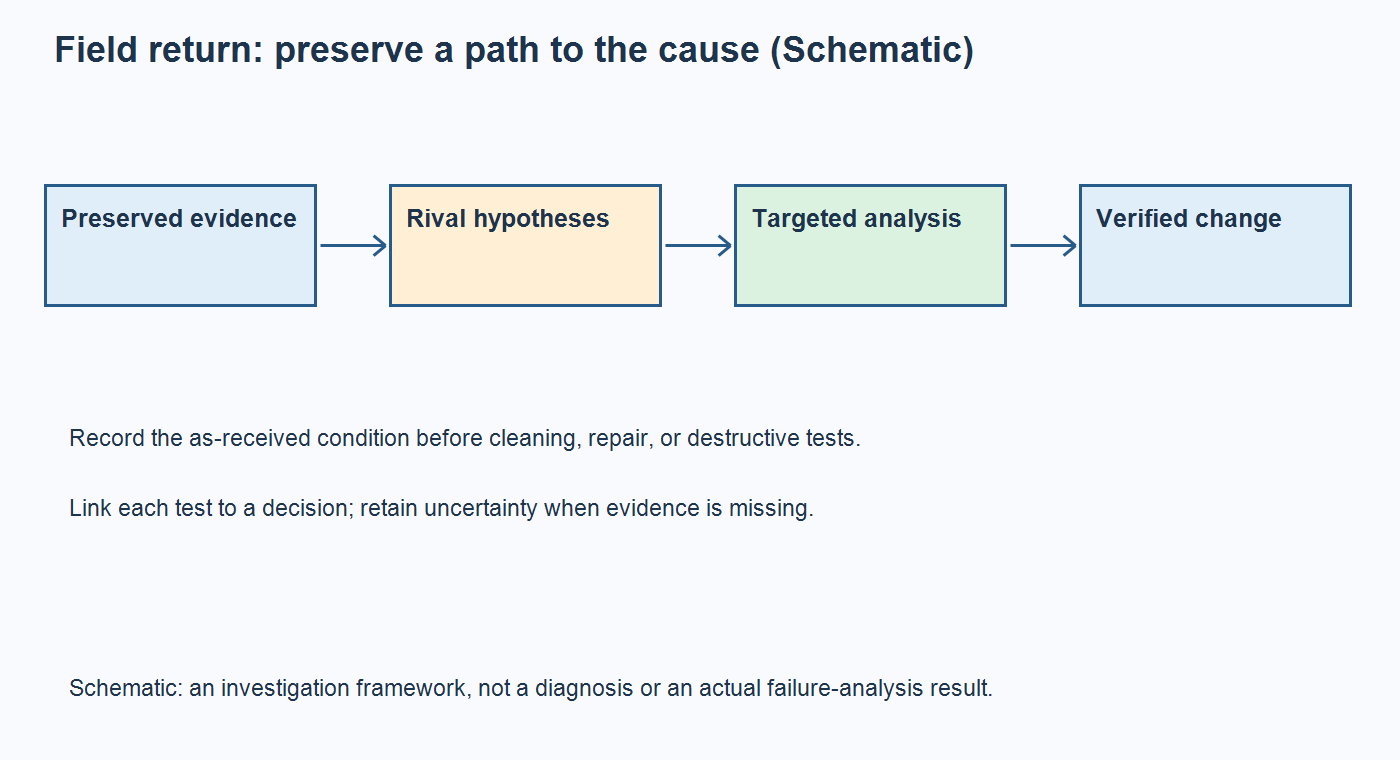
Table of Conent
Table of Conent
Blister packer PCB field failures should be investigated from the returned assembly’s original condition, not from a list of presumed manufacturing defects. Preserve the board, record the exact failed function and operating conditions, and isolate the electrical path before cleaning, baking, reflowing, or cutting the sample. A controller that passes a room-temperature retest can still have an intermittent fault; that result does not identify a cause or clear the affected population.
For OEM engineering and purchasing teams, the useful output is a supported mechanism, a defensible containment boundary, and a verified corrective-build requirement. An intermittent open, moisture-associated leakage, firmware state, and an installation problem need different evidence. Design susceptibility and manufacturing variation can also interact. The method below helps allocate limited returned samples and laboratory work without prematurely blaming fabrication. It does not diagnose a particular blister machine, prescribe universal test limits, or claim that OrinewPCB supplies every specialist analysis service described.
Preserve the returned board before changing its condition
Keep an identifiable as-received sample and document every intervention that could change the failure evidence. Repair and investigation have different immediate objectives: restoring operation may remove the condition needed to explain the return.
Photograph both sides, connectors, deposits, damaged areas, mounting points, labels, and packaging. Link the return identity to the PCB and BOM revisions, firmware, assembly lot, shipment, service history, and installed machine configuration. Record whether anyone already cleaned, dried, reseated, reflashed, or repaired it. Keep relevant cables and mating connectors identifiable, with storage and handling agreed for the suspected evidence.
Do not bake a moisture-associated return or wash visible residue as a routine first step. Agree any necessary preservation treatment with the investigating laboratory. If only one failed board exists, identify which observations can be completed before a proposed intervention consumes it.
NASA’s staged failure-analysis approach uses nondestructive and then increasingly invasive techniques to determine a cause or mechanism. That is a useful way to plan sample use, not a mandatory PCB acceptance sequence or a claim that every available laboratory method is needed.
Separate the failed function from the suspected mechanism
Describe the earliest verified loss of function before naming a physical cause. “Controller resets after warm-up” is an observation; “bad via plating” is a hypothesis that still needs a location, mechanism, and causal evidence.
Establish the approved bench boundary and preserve the machine’s safety arrangements. Identify which functions belong to the board, an external drive, a PLC, or other equipment. Capture the relevant supply, reset, command, feedback, and firmware state under a reproducible stimulus. The controller fault-isolation guide explains how to locate the first disagreement and check measurement effects; the same reasoning requires this blister controller’s own interfaces and limits.
Compare an appropriate reference board using the same fixture, firmware, harness, load, and acquisition settings. A different revision or a dry laboratory setup may explain why a reference passes. Record the duration and conditions of a no-fault-found result instead of treating it as proof that the field report was wrong.
Use observations to choose between competing hypotheses
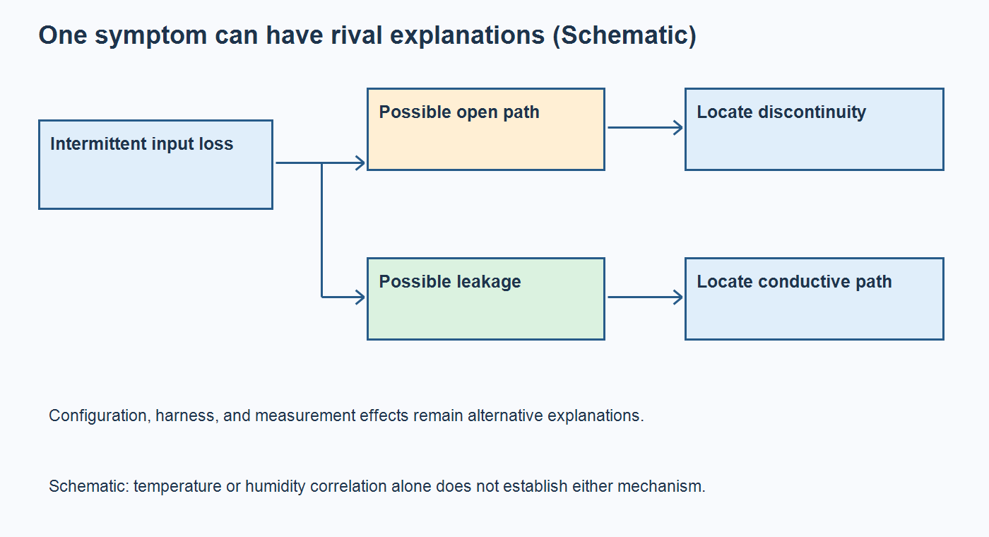
Choose tests for their ability to distinguish explanations, not for their sophistication. An intermittent input loss can result from an opening connection, a leakage path shifting a logic level, or a configuration problem; the symptom alone cannot choose among them.
| Possible explanation | Evidence to seek | What remains unproven |
|---|---|---|
| Intermittent open in a joint, connector, or via path | Localized continuity or signal interruption under an approved, monitored reproduction condition | A temperature association alone does not locate the discontinuity or prove fabrication error |
| Surface leakage or electrochemical migration | Electrical leakage localized to the relevant nodes, preserved surface evidence, and suitable contamination analysis | Visible residue or humidity correlation alone does not establish a conductive failure path |
| Internal conductive anodic filament formation | Reduced insulation between identified conductors plus targeted internal physical evidence | A photograph of surface dendrites does not demonstrate an internal laminate mechanism |
| Installation, firmware, or measurement condition | A controlled comparison of the specific harness, configuration, or observation path | A passing replacement board does not independently prove that the original board was defective |
When manufacturing and field records need to be reconciled, share the return history and controlled build files with OrinewPCB, the quantities at risk, and the proposed investigation boundary so the assembly review can identify required records, responsibilities, and quotation assumptions.
DTU research on contamination and bias, published as a 2014 conference abstract, reports interactions among contamination, humidity, and electrical conditions. It supports considering those variables together, not diagnosing every humid-environment failure as migration. NPL describes CAF as a lower-resistance path forming inside the laminate. Keep that internal mechanism distinct from surface growth.
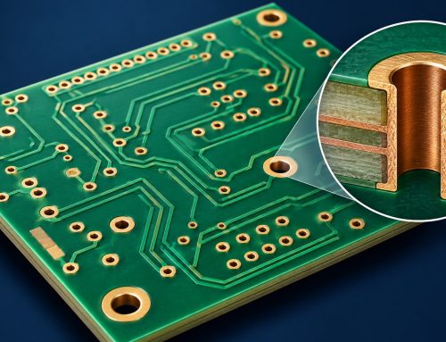
The official OrinewPCB video illustrates copper-dendrite migration as one possible field-failure mechanism. Its topic does not establish the cause of a returned blister controller; the investigation still needs the measured path and corroborating evidence.
Authorize destructive analysis around one decision
Before sectioning, extracting residues, or removing a component, agree which unresolved decision the operation will answer and what evidence it will destroy. A laboratory method is useful only when its target and limitations match the localized hypothesis.
| Decision before proceeding | Record to approve | Reason to pause |
|---|---|---|
| Where is the suspected failure path? | Net, component, joint or via coordinates and the electrical observations connecting it to the symptom | The proposed cut or extraction area is selected only from a generic defect list |
| What alternative explanation is being tested? | Expected findings that support or weaken each remaining hypothesis | Any visible anomaly would automatically be called the root cause |
| What evidence and samples remain? | Pre-intervention images and measurements, retained controls, sample allocation, and any unavailable reference | The only return would be consumed before its original condition is adequately recorded |
| What happens after the result? | Stop, redirect, or release-review criteria and the owner authorized to decide | More testing is planned regardless of whether it can change the decision |
Specify the laboratory deliverable before authorizing the work. Ask for sample identities, preparation steps, instrument method, relevant detection limits, annotated images with locations, raw electrical results where applicable, and a distinction between observations and interpretation. A report should explain whether the findings support the failed electrical path, what alternative causes remain, and which further test could resolve them. If the sample was already cleaned or repaired, require that limitation in the conclusion rather than treating missing evidence as a negative finding.
A microsection exposes a selected plane; it does not examine every possible site. Similarly, a normal X-ray result cannot exclude every fine crack or leakage mechanism. Ask the laboratory how preparation artifacts, detection limits, and sampling location affect interpretation. Preserve coordinates and intermediate images so the electrical and physical observations remain connected.
Separate design exposure from manufacturing variation
Connect the confirmed mechanism to the conditions that created it before assigning responsibility or changing the specification. A physical crack identifies damage; further evidence is needed to distinguish process variation, design stress, handling, installation, and their interactions.
For example, a localized discontinuity associated with a via still needs evidence of its formation and loading history. Review the released construction and relevant fabrication records alongside assembly, handling, and service exposure. Finding the failure site is a necessary step; it does not by itself establish which specification or process should change.
Compare affected and unaffected units against the installed population and exposure history. A lot with more returns may also have more shipped units, longer service, or a different installation. Without those denominators and conditions, a return count is not a comparable failure rate. Record manufacturing changes, panel position where available, rework, mounting, and field exposure without assuming any one association establishes causality.
As a hypothetical example, the same controller revision may be used with two mounting arrangements. If returns cluster in one arrangement, compare its loading and handling before attributing the cluster to the board lot. Conversely, evidence of a localized process excursion may justify lot-focused containment. Missing comparison data should remain an explicit uncertainty.
Release a corrective build with evidence and limits
Approve a corrective build only when the change, its verification, and the remaining uncertainty are recorded together. A repaired return that passes once does not demonstrate that future production will avoid the mechanism.
Update the relevant fabrication note, material or process control, assembly instruction, mounting constraint, firmware configuration, or test requirement. Keep those revisions aligned with the blister-packer design-release guide. Reproduce the relevant original condition under an approved plan, check the affected functions, and define the follow-up evidence needed to assess recurrence.
The purchased full turnkey PCB assembly scope can be reviewed for fabrication, sourcing, and assembly coordination. Specialist laboratory work, environmental testing, and responsibility for machine-level acceptance require separate confirmation.
Preserve the original evidence, challenge rival explanations, and spend samples only on decisions that matter. For a replacement or revised assembly evaluation, provide the corrective-build package and acceptance evidence to OrinewPCB with Gerbers, BOM, placement data, quantities, firmware/test requirements, and the approved changes so manufacturing scope and quotation assumptions can be reviewed together.
Latest Blog
Contact Info
Phone: +86-755-82882936
Email: [email protected]
WhatsApp: +86-13570802455
Wechat: +86-13570802455
Address: 2nd floor,D Bldg.,Electric Link Technology Bldg.,Gongming,Guangming New Dist.,518106 Shenzhen, China