
Shrink-Wrap Controller PCB Cost: Protect Thermal Margin
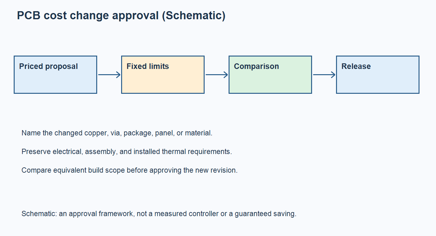
Table of Conent
Table of Conent
Shrink-wrap controller PCB cost can be reduced without consuming thermal margin only when the proposed construction still meets the released electrical, assembly, and installed-temperature requirements. Compare a defined baseline with a defined candidate. Ask the manufacturer to identify the actual saving, then have the design owner approve the evidence needed before that candidate replaces the qualified build.
Start with changes that remove unnecessary manufacturing complexity while preserving required behavior. Reducing copper, deleting thermal vias, shrinking the board, or substituting a power device can change both heat generation and heat removal. A lower bare-board price does not establish a lower cost per accepted controller. This guide addresses construction-change decisions for a controller that may operate near sealing equipment or inside a warm cabinet. It does not assume that heater or motor power flows through the PCB; establish the machine’s actual architecture before applying any current or thermal calculation.
Define the cost reduction without changing the acceptance target
Write the candidate as a controlled change to the existing build, with the acceptance target held constant. “Reduce PCB cost” is too broad to approve. “Evaluate a different copper construction while retaining the released load and temperature limits” identifies a decision that engineering and purchasing can review together.
Record the baseline PCB revision, stackup, BOM population, mounting arrangement, enclosure conditions, and relevant operating modes. Identify which temperatures are limited: semiconductor junction, package case, board location, connector, or nearby material. A maximum component rating and an internal design-margin target serve different purposes; preserve the approved basis rather than silently replacing one with the other.
A shrink-wrap controller may only send low-voltage commands to external heaters and drives. Another architecture may switch significant load current on the board. That distinction determines whether a cost proposal changes a current-carrying path, a local device heat path, or mainly manufacturing complexity. The installed controller thermal-design guide explains the broader board-versus-cabinet boundary; use it to establish the baseline before comparing prices.
Screen copper changes with loss, not copper weight alone
Evaluate the finished conductor geometry and its electrical loss before approving a thinner copper construction. For a simplified rectangular conductor, resistance is rho times length divided by width times thickness. At a fixed current, resistive heating is current squared times resistance. These relationships screen a proposal; they do not predict the complete board temperature.
Consider an illustrative comparison at the same length, resistivity, and current. If thickness is halved while width stays unchanged, the cross-sectional area halves, resistance doubles, and electrical heating doubles. If width is doubled as thickness is halved, the original cross-sectional area and idealized resistance return. The wider route, however, occupies more space and can change the surrounding layout.
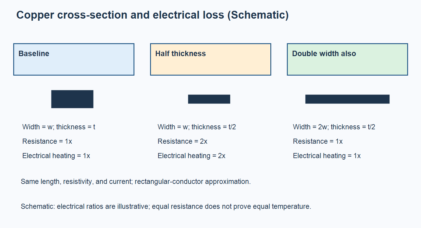
This is why a request to replace one copper-weight label with another is incomplete. Ask for the finished-copper requirement, actual narrow sections, pad transitions, via paths, and allowable voltage drop. Temperature-dependent resistance and nonuniform geometry need appropriate treatment in the real design. Do not use the illustrative ratios as a supplier tolerance or a universal current-rating rule.
Preserving a route’s resistance also does not preserve every heat-removal path. A plane may spread heat from a package even where it is not the main load-current route. Conversely, extra copper on an unrelated net may contribute little to the hot spot being investigated. Keep electrical loss and thermal spreading as separate questions in the change record.
Challenge each fabrication saving against its assembly consequence
Request a manufacturable candidate rather than deleting a costly feature in isolation. A fabrication simplification can move work into soldering, inspection, mechanical support, or rework. The useful comparison includes those consequences before either party commits to the new construction.
TI’s QFN and SON attachment guide, revised in December 2023, discusses exposed-pad attachment and the interaction between thermal vias and solder-volume loss. Its examples require application-specific process development. They are not permission to remove a via treatment or reuse a generic land pattern without checking the selected package and assembly process.
For a specific proposal, share the baseline stackup and proposed construction changes with OrinewPCB so manufacturing assumptions, affected assembly steps, and the scope of the comparison can be clarified before pricing the candidate.
| Proposed saving | What may change | Evidence before approval |
|---|---|---|
| Reduce copper or remove a layer | Conductor loss, heat spreading, routing, and electrical reference paths | Reviewed finished construction, loss assessment, affected electrical checks, and thermal comparison |
| Change thermal-via count or treatment | Heat transfer and solder behavior beneath a package | Package-specific land-pattern review, assembly evidence, and relevant thermal results |
| Shrink the board or improve panel utilization | Component spacing, support, connector access, and heat-spreading area | Panel and mechanical review with installed-configuration checks where affected |
| Change laminate or surface finish | Required material properties, solderability, storage, and process compatibility | Approved material definition and a review of the affected fabrication and assembly requirements |
| Use an alternate power component | Loss, package heat path, drive conditions, and assembly requirements | Exact-part comparison and design-owner approval with the necessary electrical and thermal evidence |
Keep soldering-process temperature separate from operating temperature. A thinner or differently distributed copper structure may require a process review even when the installed controller stays within its operating limits. The shrink-wrap mixed-technology assembly sequence provides context for the interactions between reflow, through-hole operations, inspection, and later handling.
Compare proposed savings on a controlled build basis
Compare the same accepted deliverable at the same quantity and revision basis. Separate recurring fabrication and assembly changes from new tooling, process development, test fixtures, qualification work, and inventory exposure. A saving on a bare board can disappear when the assembled controller requires additional manual work or a new validation fixture.
Ask whether the comparison retains the same sourcing constraints, programming, inspection, functional-test coverage, records, and packaging. Identify excluded work and who will perform it. If a cost proposal includes fewer inspections or tests, treat that as a coverage change requiring its own risk decision, rather than assuming the cheaper quote represents the same product.
OrinewPCB’s video below discusses sourcing and BOM cost-reduction candidates after product finalization. Use it as a starting point for identifying proposals, alongside the construction review. Pin compatibility or a purchasing opportunity alone does not approve an alternate: the changed unit still needs the electrical, thermal, and process evidence appropriate to that change.
Keep quoted savings distinct from estimated future savings and unresolved costs. State which quantity can actually use the new revision and which existing boards, components, stencils, or fixtures remain usable. Purchasing can then compare an implementable change instead of multiplying a headline unit-price reduction by an unverified lifetime volume.
Recheck the changed heat path in the installed controller
Compare baseline and candidate under documented conditions that represent the affected thermal requirement. A room-temperature power-on pass cannot establish installed thermal margin. Keep the mounting, enclosure, load state, and measurement method visible so a cooler-looking result is not simply a different test.
TI’s semiconductor thermal-metrics guide, revised in March 2024, explains that junction-to-ambient thermal resistance depends on the test board and environment as well as the package. Do not apply a data-sheet value blindly to infer the junction temperature of a modified assembly. A measured case or board temperature also needs an appropriate interpretation before it supports a junction-limit decision.
| Comparison item | Keep or record for both builds | Decision boundary |
|---|---|---|
| Configuration | PCB/BOM revision, firmware, mounting, and interface materials | Unrecorded differences prevent attribution to the proposed change. |
| Operating condition | Supply, load sequence, duty cycle, cabinet ambient, and relevant cooling state | A lighter load or cooler environment is not equivalent evidence. |
| Temperature measurement | Measurement location, method, sensor attachment, and applicable uncertainty | Case, board, air, and junction temperatures are not interchangeable. |
| Time and repeatability | Stabilization criterion, observation period, and agreed sample basis | A brief transient or isolated favorable unit cannot silently replace the required test. |
| Acceptance | Released limits, design-margin requirement, results, and unresolved exceptions | Approval requires the defined criteria, not merely a lower average temperature. |
Change one controlled factor where practical, and record combined changes when separation is impossible. Select the necessary repeat tests with the DVT change-review method. Thermal checks do not automatically clear altered current paths, electrical performance, solder joints, mechanical support, or machine-level requirements.
Release the qualified change as a complete assembly package
Approve the new construction only after the priced scope and required evidence describe the same revision. The release should state the accepted change, its supporting results, remaining conditions, and the person authorized to approve it. Retain the baseline record so future substitutions do not erase the comparison.
Send updated fabrication data, stackup, BOM, placement files, assembly drawings, quantities, and relevant programming and test requirements together. Highlight the changed copper, vias, package, panel, or thermal interface. OrinewPCB’s full-turnkey PCB assembly scope connects fabrication, component sourcing, and assembly; agree any specialized installed thermal validation separately with the responsible parties.
A useful cost reduction removes paid complexity while preserving the requirements that make the controller acceptable. When the candidate and its approval basis are ready, provide the revised assembly files and comparison requirements so OrinewPCB can review the manufacturing package, clarify sourcing and assembly responsibilities, and define the quotation scope.
Latest Blog
Contact Info
Phone: +86-755-82882936
Email: [email protected]
WhatsApp: +86-13570802455
Wechat: +86-13570802455
Address: 2nd floor,D Bldg.,Electric Link Technology Bldg.,Gongming,Guangming New Dist.,518106 Shenzhen, China