
Palletizer Controller PCB Thermal Design: Budget Board and Cabinet Heat
Table of Conent
Table of Conent
A palletizer controller PCB should be designed for the temperature it actually sees in its installed cabinet, not for room air on a bench. Start by separating heat generated on the board from heat generated by servo drives, power supplies, and other cabinet equipment. Then calculate losses for the board’s operating states, provide a credible heat path, and test the assembled unit at the specified cabinet ambient. A larger copper pour cannot solve heat produced elsewhere in the enclosure.
Define the thermal boundary before changing the PCB
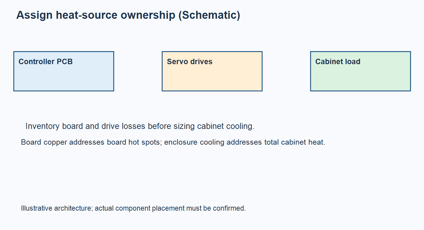
“Palletizer control board” can describe very different architectures. One machine places logic, I/O isolation, communications, and low-voltage regulation on a PCB while the servo drives are separate modules. Another may carry a motor power stage on the same assembly. Ask the machine designer for an enclosure layout and a power tree before selecting copper weight, thermal vias, or a heat sink. Mark each source of heat as board, module, or cabinet equipment; record where its heat is expected to leave.
The enclosure supplier’s industrial enclosure guidance treats installed equipment dissipation and ambient conditions as inputs to cooling selection. That supports a useful ownership rule: if a drive warms the cabinet air, the cabinet thermal design owns that load even when the controller PCB is inside the same box. A PCB heat spreader may reduce a component hot spot, but it does not remove the drive’s heat from a sealed cabinet.
The physical boundary also affects responsibility at quotation time. Ask whether the controller is supplied as a bare PCBA, a board with a metal carrier, or a fully wired cabinet. State who supplies the interface material and who verifies contact pressure after installation. If those duties are left between suppliers, a passing board test can coexist with an overheating installed assembly. This ownership check is especially important when the same controller PCB is used in more than one cabinet size or drive configuration.
Build a loss budget around real operating states
List the maximum permitted cabinet air temperature at the board, the controller’s mounting position, nearby hot equipment, and the duty cycle of each operating mode. A palletizer can spend long intervals waiting, then switch outputs and communicate intensively during repeated picks. The worst component temperature may occur during a sustained production mode rather than during a brief start-up peak. Include a credible fault or reduced-cooling state if the machine requirement calls for one.
For a switching regulator or power stage actually fitted to the board, estimate dissipation from its data sheet at the required input voltage, load, and switching conditions. For linear regulators, use the voltage drop and load current; for output devices, use conduction and switching losses appropriate to the topology. Treat these as engineering estimates until a prototype is measured. If input currents, load states, or cabinet temperatures are unknown, put them on the design-input request rather than replacing them with an arbitrary “industrial” ambient. This also helps the EMS supplier distinguish a board fabrication issue from a machine-level cooling requirement.
Analog Devices’ thermal application note frames junction temperature around power dissipation, package, PCB, heat sink, and ambient. The published package numbers are screening data; they do not measure the temperature of this board in this cabinet. Record the assumptions next to each estimated component temperature so a later component substitution does not silently invalidate the analysis.
Choose a heat path that can be assembled consistently
For each hot part, trace heat from the silicon through the package into pads, copper, vias, chassis contact, or air. The preferred path depends on the specific package and mechanical stack. Large copper regions can spread heat, but they can also affect soldering balance, clearances, and routing. Thermal vias near an exposed pad require a fabrication and assembly choice: diameter, location, fill or plug method, and solder-mask treatment. Texas Instruments’ QFN guidance discusses via placement and solder loss for that package family; it is a reason to review the chosen footprint with the assembler, not a universal via recipe.
If the design uses a heat sink or chassis contact, define flatness, interface material, attachment pressure, and service access in the mechanical drawing. A nominal heat sink that is not in reliable contact does not constitute a verified thermal path. Compare the copper-pour layout considerations with your electrical return paths and assembly drawing; do not optimize only a temperature plot. Where a board sits next to a drive, moving the drive, adding a partition, or changing cabinet cooling may offer more benefit than adding board copper.
Before requesting a prototype price, share the cabinet temperature requirement, board stackup, hot-part list, and heat-path drawing for an assembly review. This makes the quote cover the actual thermal interface and any special via processing.
Use a decision table to assign the next evidence
The table is a screening tool for the design review and RFQ. Its thresholds must come from the product’s component ratings and machine requirements, not from a generic palletizer temperature claim.
| Observed or expected condition | First design question | Evidence to request | Primary owner |
|---|---|---|---|
| Cabinet air warms when drives run, while controller dissipation is low | Is the enclosure cooling or equipment placement adequate? | Installed cabinet air map at the specified production duty cycle | Machine and enclosure designer |
| One PCB regulator or power device is a local hot spot | Can the selected package, pad, copper, and mechanical path carry its loss? | Data-sheet loss estimate, footprint review, measured case or board temperature | Electrical designer and EMS engineer |
| A component substitution changes loss or thermal resistance | Does the substitute still meet margin in the same installation? | Revised loss calculation, package data, and representative thermal test | Design authority and purchasing |
| Prototype passes on an open bench but fails in a closed cabinet | What installed condition was omitted from the bench test? | Cabinet ambient, load state, airflow, and temperature log tied to board revision | System test owner |
Set pass criteria for the hottest relevant device and for any surrounding part that may be affected by its heat. A thermal camera can locate candidates, but reflective surfaces and emissivity can mislead; verify critical points with an appropriate contact sensor or a validated measurement method. Keep the sensor location, calibration status, ambient measurement, and operating state with the result.
Validate the assembled board in the installed environment
TI’s thermal design guide explains why package metrics measured on standardized boards need care when predicting an actual system. For a palletizer controller, compare the modeled hot spots with a powered prototype in a representative enclosure. Test the documented worst relevant operating states, including the highest specified cabinet ambient and any applicable reduced-airflow condition. Log supply voltage, load, ambient, component temperature, and time to stabilization. A room-temperature functional test confirms electrical behavior under that condition; it is not a cabinet thermal qualification.
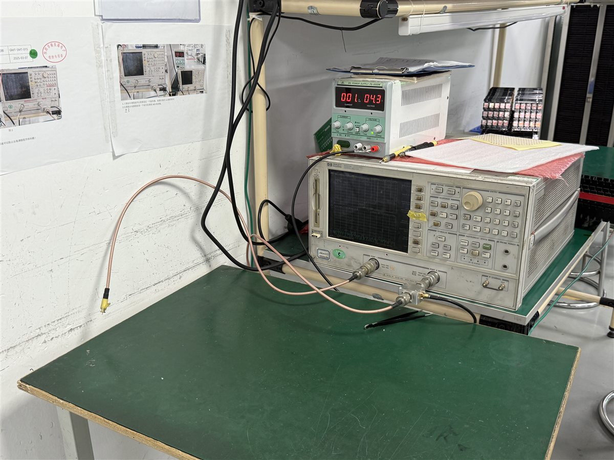
Use the environmental test selection guide to distinguish chamber exposure, powered operation, and installed-system validation. If a hot spot fails, change one controlled variable at a time: component choice, copper/via pattern, interface, layout position, or cabinet cooling. Re-test with the relevant revision. A successful bare-board calculation does not clear a populated board with different solder voiding, attachment, or neighboring loads.
Release a quote-ready thermal package
Purchasing should send the EMS supplier the PCB fabrication files, BOM with approved alternates, assembly drawings, hot-part and heat-interface requirements, expected load states, and the required test scope. Call out any filled vias, copper weight, heat sink, thermal pad, fixture, sensor point, or traceable test record separately. The assembly drawing checklist helps put build-critical notes where the factory will see them. A full turnkey assembly scope can combine sourcing and build responsibility, but the buyer still needs to define system-level acceptance and approve substitutions.
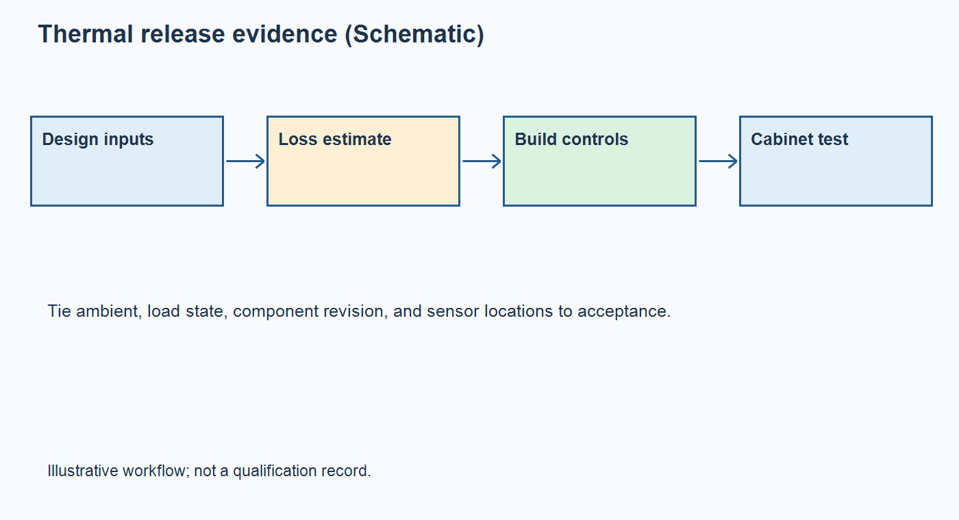
Ask for a quote that distinguishes board manufacture, special thermal-via processing, interface hardware, fixture work, and powered thermal validation. That split exposes cost changes before a production build. When an alternate regulator or package is proposed, compare its loss and thermal path under the same conditions instead of accepting a pin-compatible designation alone.
The release decision is specific: each heat source has an owner, each critical component has a documented margin at the specified condition, and the assembled controller has a repeatable installed test. Send the controlled design package and cabinet conditions for a manufacturing and test-scope review when those inputs are ready.
Latest Blog
Contact Info
Phone: +86-755-82882936
Email: [email protected]
WhatsApp: +86-13570802455
Wechat: +86-13570802455
Address: 2nd floor,D Bldg.,Electric Link Technology Bldg.,Gongming,Guangming New Dist.,518106 Shenzhen, China