
PCB Assembly Drawing Checklist: 7 Errors That Delay PCBA
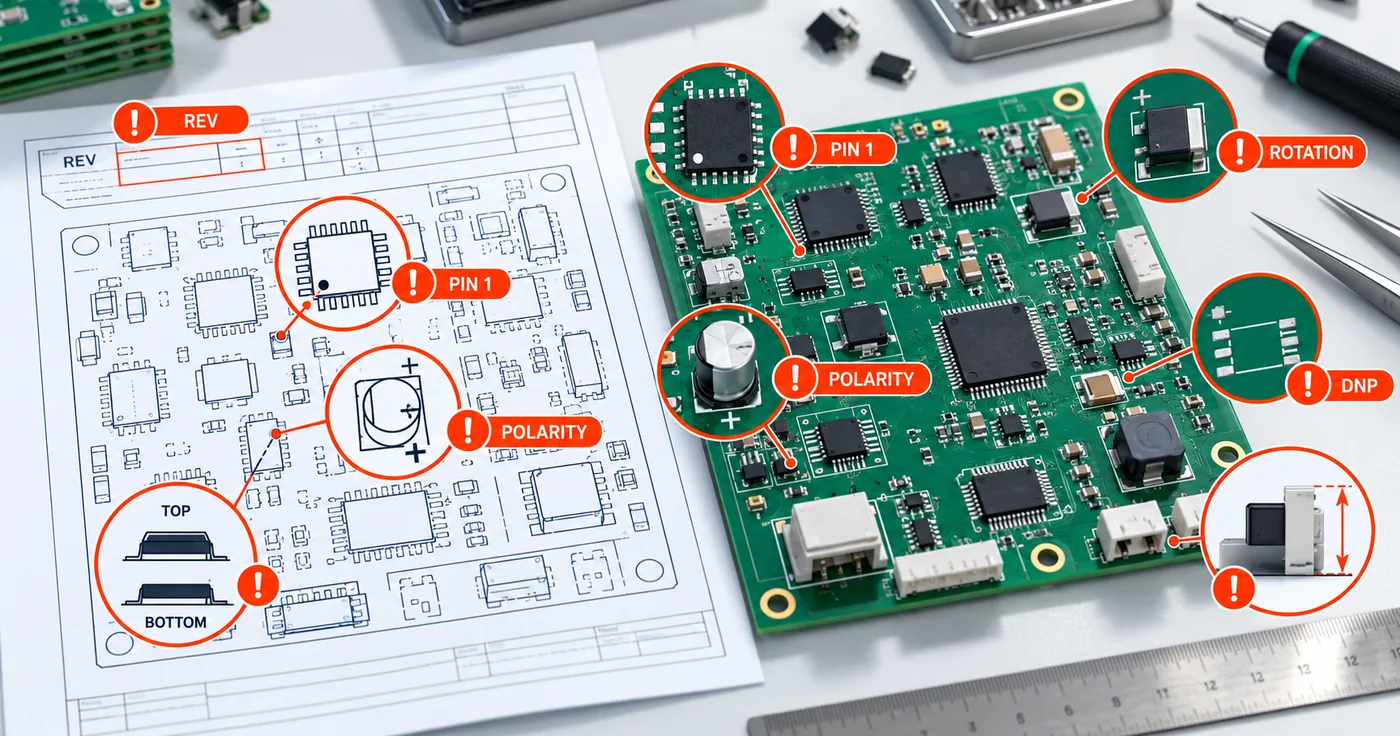
Table of Conent
Table of Conent
A PCB assembly drawing is not a decorative printout. It is the document that resolves the manufacturing decisions your Gerber files, bill of materials (BOM), and component placement file cannot explain on their own. If those files disagree, the assembly drawing often becomes the first place an engineer looks for the intended build.
That is why a board can have valid fabrication data and still be delayed at quoting, design-for-assembly review, or first-article inspection. An unclear revision, an ambiguous polarity mark, or a missing do-not-populate note creates a question that must be answered before production can safely proceed.
This PCB assembly drawing checklist focuses on seven errors that commonly turn a ready-to-build PCBA package into an engineering clarification. Use it before requesting a quote and again before releasing production data.
Contents
- What a PCB assembly drawing must do
- Assembly drawing vs. Gerber, BOM, and pick-and-place files
- The seven errors to catch before release
- A practical release-review example
- How to review a PCB assembly drawing
- The complete turnkey PCBA release package
- Watch: what to send for a fast, accurate PCB quote
- Copyable PCB assembly drawing checklist
- Frequently asked questions
What a PCB assembly drawing must do
A useful assembly drawing gives a manufacturer an unambiguous visual reference for how the populated board should look. It should identify the product and revision, distinguish the top and bottom views, show reference designators, communicate orientation and polarity, flag intentional omissions, and call out assembly details that are not reliably expressed elsewhere.
The drawing does not replace machine-readable data. It complements it. A strong release package lets the assembler compare the visual intent in the drawing with the component identities in the BOM and the X/Y/rotation data in the centroid or component placement list (CPL). This cross-check supports the broader printed circuit board assembly process, where released engineering data must remain consistent from incoming review through placement, soldering, inspection, and test.
For a broader list of files normally needed for manufacturing, see OrinewPCB’s guide to PCB assembly file requirements.
Assembly drawing vs. Gerber, BOM, and pick-and-place files
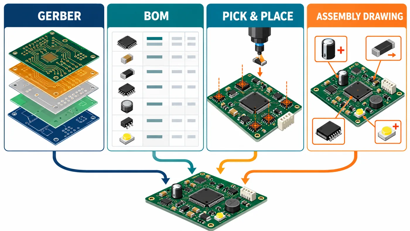
Four file types are frequently confused even though they serve different purposes:
- Gerber or ODB++ data defines the physical PCB layers, copper, solder mask, legend, paste, and board profile.
- The BOM defines which component belongs at each reference designator, including the manufacturer part number, quantity, and approved substitutions.
- The pick-and-place file provides the component reference, X/Y location, side, and rotation used to program placement equipment.
- The assembly drawing provides a human-readable view of intended placement and the special instructions needed to interpret the other files correctly.
Think of these files as a cross-checking system. If the BOM says C17 is fitted, the CPL should include C17 and the drawing should not mark it DNP. If the CPL identifies U3 on the bottom side, the drawing must show U3 in the bottom assembly view. Any conflict should be resolved before the data package is released.
The seven errors to catch before release
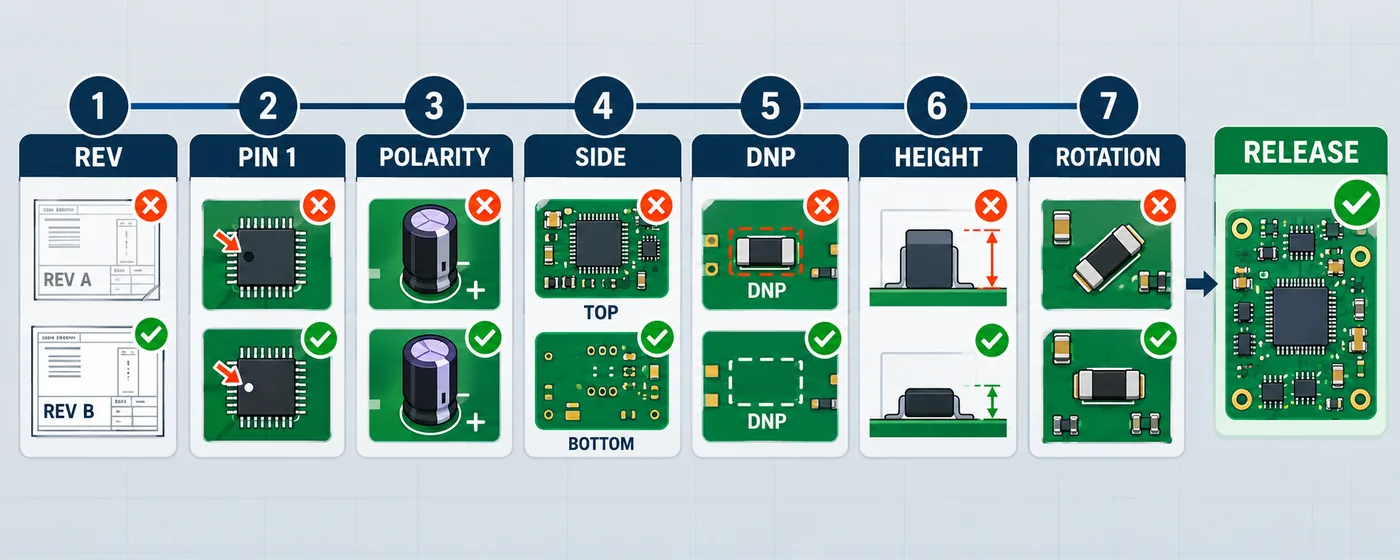
1. The drawing revision does not match the BOM and PCB data
A release package should behave like one controlled record. Put the assembly number, drawing number, revision, and release date in the title block. Then verify that the same revision is reflected in the BOM, fabrication data, CPL, test instructions, and purchase order.
Do not rely only on filenames such as final.zip or revB_latest.xlsx. Those names are easy to misread or reuse. A simple revision table on the drawing—showing the revision, date, change summary, and approver—makes the intended build much easier to establish.
2. Pin 1 and keyed connector orientation are unclear
Every orientation-sensitive IC and connector needs a mark that survives printing and PDF export. Use a clear dot, chamfer, notch, or numbered pin callout. For board-edge and cable connectors, show the mating direction when a mirrored installation would still appear mechanically possible.
Check the drawing against the footprint, component datasheet, and 3D view. A silkscreen mark alone is not enough if it sits under the component or becomes difficult to see after assembly.
3. Polarity conventions are inconsistent
Diodes, LEDs, electrolytic capacitors, batteries, and other polarized parts can use different marking conventions. For example, the stripe on a diode normally identifies the cathode, while the stripe on many aluminum electrolytic capacitors identifies the negative terminal. A generic “stripe side” note therefore creates risk.
Label the actual electrical meaning—such as cathode, anode, positive, or negative—and make the symbol consistent across the assembly drawing, silkscreen, schematic, and inspection criteria.
4. Top and bottom views can be interpreted in two ways
A bottom-side image may be shown as viewed through the board, or as if the board has been physically flipped. Both conventions exist. Label each view explicitly and add a note such as “bottom view shown from bottom side” or “bottom view mirrored from top.”
Add a board outline, a distinctive connector, or a datum marker to make the orientation visually obvious. This is especially important for rectangular boards whose two sides otherwise look similar.
5. DNP and product-variant rules conflict
Do-not-populate (DNP/DNI) decisions must agree in every source. If R9 is omitted in Variant A, the BOM should identify that state, the drawing should mark R9 as not fitted, and the placement data should follow the assembler’s agreed convention. Do not assume that deleting a line from the BOM is sufficient; the absence may be interpreted as an accidental omission.
For multiple product variants, provide a clear configuration matrix. List each variant, its applicable revision, and the reference designators that change. The same controls used to manage PCB assembly variants and DNP parts should govern the drawing, BOM, and CPL together. Avoid releasing several nearly identical drawings with no obvious master relationship.
6. Mechanical and secondary-operation notes are missing
Placement data cannot fully describe every mechanical requirement. Add notes for maximum component height, adhesive, staking, conformal coating keep-outs, thermal interface materials, press-fit components, hand-soldered wires, shields, labels, hardware, and connector alignment when these requirements apply.
Use a dimensioned detail or section view for critical heights and overhangs. If the assembled board must fit an enclosure, include the relevant mechanical drawing or 3D model in the release package rather than asking the assembler to infer the limits.
7. Rotation and origin conventions are not validated
CAD systems, libraries, and placement machines do not always share the same zero-degree convention. The CPL can therefore be syntactically correct while a polarized or asymmetric part appears rotated by 90 or 180 degrees.
Before release, compare the CPL against a rendered assembly view. Pay special attention to fine-pitch ICs, connectors, diodes, LEDs, and unusual footprints. Include the units, coordinate origin, side convention, and rotation direction in the file header or accompanying README. Visual checking is the fastest way to expose a convention mismatch.
A practical release-review example
Consider a controller board labeled Revision B, Variant A. The BOM lists R9 as fitted, the assembly drawing labels R9 “DNP,” and the CPL contains placement coordinates for R9. At the same time, connector J2 has a keyed housing, but neither the drawing nor the silkscreen identifies the mating direction.
This package should not be released. The engineer first decides whether R9 is fitted for Variant A, then updates all three files to the same state. Next, the engineer adds a J2 orientation callout and checks it against the connector datasheet and enclosure model. Finally, the files are regenerated under a single Revision B release and reviewed together.
The important lesson is that each individual file can look reasonable while the package as a whole remains ambiguous. Cross-file consistency—not merely file presence—is the real release criterion.
If the revision, population, or rotation rules still need a manufacturer-side check, share the controlled build package for engineering review, including the Gerber or ODB++ data, BOM, CPL, assembly drawing, build quantity, and applicable test requirements. The review can then identify file conflicts and clarify the scope needed for fabrication, sourcing, assembly, and quotation.
How to review a PCB assembly drawing
- Freeze the intended variant. Confirm the product name, assembly number, revision, and build option before checking details.
- Render both sides. Export readable top and bottom views with reference designators and orientation marks visible at normal zoom.
- Cross-check reference designators. Compare the drawing, BOM, and CPL for missing, duplicated, or extra designators.
- Audit sensitive parts. Review pin 1, polarity, keyed connectors, LEDs, switches, and asymmetric mechanical parts against datasheets.
- Validate variants and DNPs. Make every population decision explicit and consistent across the package.
- Review mechanical constraints. Confirm height limits, keep-outs, hardware, adhesives, labels, coating, and enclosure interfaces.
- Run a visual CPL check. Load the coordinate file into a viewer or your assembler’s DFM portal and inspect side and rotation.
- Release one controlled package. Archive the exact approved files together and avoid sending later corrections as isolated email attachments.
The review should also consider inspection and test access. OrinewPCB’s guide to PCB design for testability explains how test-point planning affects ICT and functional test. Fabrication notes that affect stackup, materials, drill data, or controlled dimensions should also align with the documented PCB manufacturing capabilities used to assess the build.
The complete turnkey PCBA release package
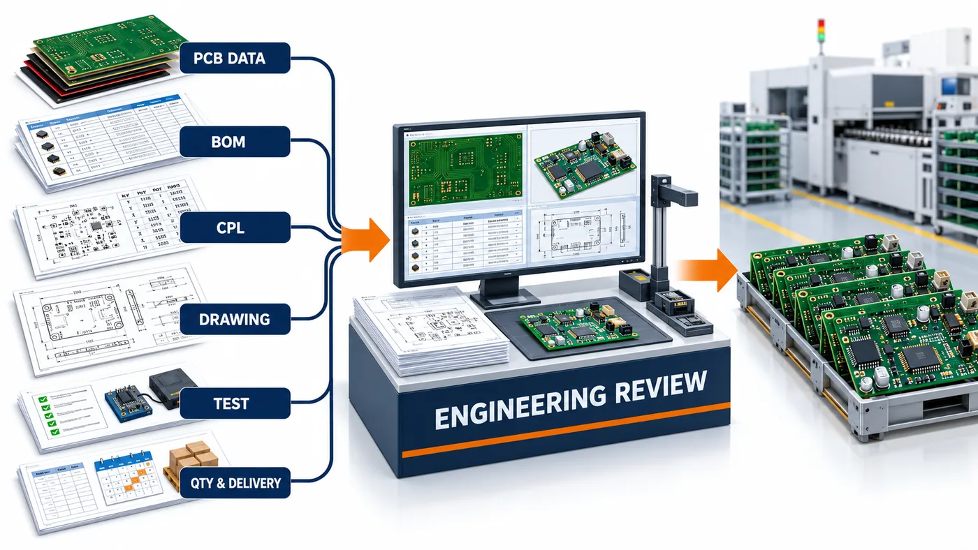
The assembly drawing is only one part of a quote-ready package. For a turnkey PCBA request, normally include:
- Gerber or ODB++ fabrication data, drill files, and a fabrication drawing;
- a BOM with manufacturer part numbers and approved alternates;
- the pick-and-place/CPL file with units, origin, side, and rotation conventions;
- top and bottom assembly drawings with revision control;
- schematic, when it can support engineering review and troubleshooting;
- test requirements, programming files, firmware version, and acceptance criteria;
- special process notes, mechanical files, panel requirements, and packaging instructions;
- order quantity, prototype or production status, target lead time, and delivery destination.
A coordinated supplier review is most useful when the same released package governs PCB fabrication, component sourcing, assembly, inspection, and testing. Keep the approved revision together so later clarifications do not create a second source of truth.
Watch: what to send for a fast, accurate PCB quote
This short OrinewPCB video explains the five categories of information that help a manufacturer prepare an accurate PCB or PCBA quote. It complements the checklist above by showing how technical files, quantities, materials, lead time, and special requirements work together.
Copyable PCB assembly drawing checklist
Use this compact version during release review:
- Product name, assembly number, revision, date, and units are present.
- Drawing, BOM, PCB data, CPL, test files, and purchase order use the same revision.
- Top and bottom views are clearly labeled with an unambiguous viewing convention.
- All reference designators are readable and agree with the BOM and CPL.
- Pin 1, polarity, LED direction, and keyed connector orientation are explicit.
- DNP/DNI parts and product variants are consistent in every file.
- Component side, X/Y location, rotation, coordinate origin, and units are validated.
- Height limits, keep-outs, adhesives, coatings, hardware, labels, and hand operations are called out.
- Critical dimensions and enclosure interfaces have supporting mechanical data.
- Test, programming, firmware, inspection, and acceptance requirements are included.
- A rendered placement review has been completed for both sides.
- The approved files are archived and transmitted as one controlled release package.
Frequently asked questions
Is a PCB assembly drawing required if I already have a pick-and-place file?
It is strongly recommended. A pick-and-place file provides machine-readable coordinates and rotations, but it rarely communicates variant rules, mechanical notes, polarity intent, hand operations, or the visual context needed to resolve an inconsistency.
What format should a PCB assembly drawing use?
PDF is the safest review format because it preserves the intended page and is easy to annotate. Native CAD files can also be useful, but they should not be the only readable drawing supplied. Export at a scale and resolution that keeps reference designators legible.
Should DNP components appear in the pick-and-place file?
There is no universal convention. Some workflows omit DNP parts; others include them with a population-status field. Agree on the format with the assembler and make sure the BOM, drawing, and CPL tell the same story.
How should bottom-side components be shown?
Either a direct bottom view or a mirrored top-reference view can work, provided the convention is labeled clearly. Add a datum, board feature, or connector outline so the viewer cannot mistake left for right.
What is the most important final check before sending an RFQ?
Confirm that every file belongs to the same revision and variant. Then visually compare the assembly drawing with the BOM and rendered CPL. This single cross-file review catches many of the errors that otherwise become quotation questions or production holds.
After the drawing, BOM, CPL, and fabrication data agree, provide the released fabrication and assembly package with the build quantity, approved substitutions, inspection or test requirements, and target delivery window. That gives the engineering and sourcing review a defined baseline for resolving manufacturability questions and preparing the quotation scope.
Latest Blog



Contact Info
Phone: +86-755-82882936
Email: [email protected]
WhatsApp: +86-13570802455
Wechat: +86-13570802455
Address: 2nd floor,D Bldg.,Electric Link Technology Bldg.,Gongming,Guangming New Dist.,518106 Shenzhen, China