
DVT Change Review: Decide Which PCB Tests Need Repeating
Table of Conent
Table of Conent
A PCB change during design validation testing does not automatically require repeating every test, but it should never be closed with “minor change” as the only rationale. The correct retest scope comes from the requirements affected, the interfaces touched, the risks introduced, the evidence invalidated, and the production configuration that will carry the change.
This guide gives hardware teams a practical DVT change-review method. It connects schematics, PCB layout, components, firmware, mechanics, manufacturing, and test evidence so the team can decide what to repeat and document why. If a revision is moving toward another build, AssyPCB can review the PCB assembly package and prepare a quotation when you provide the controlled files, quantities, change summary, and required verification.
What DVT is supposed to prove
Design validation testing is commonly used to show that a product design meets its defined requirements under representative operating and environmental conditions. Company stage names vary, so “DVT” should not be treated as a universal standard term. The controlled verification and validation plan, product requirements, risk file, and customer or regulatory obligations define what the evidence must demonstrate.
Verification asks whether the realized product meets specified requirements. Validation asks whether it fulfills the intended use and stakeholder need. NASA systems-engineering guidance distinguishes these objectives and uses a requirements verification matrix to link each requirement to inspection, analysis, demonstration, or test. FDA design-control guidance similarly emphasizes verified design changes and risk-based validation where applicable. These principles are useful even when a product is outside those regulated contexts.
After a PCB change, the team should preserve prior evidence that remains valid, retire evidence that no longer represents the configuration, and generate new evidence for affected requirements. The result is a controlled delta-verification plan, not a reflexive full rerun and not an undocumented waiver.

Freeze the baseline before assessing the change
Start by identifying the exact baseline that passed or entered DVT. Record the PCB fabrication revision, assembly revision, BOM revision, approved alternates, firmware or FPGA version, enclosure and harness revisions, test fixture and script versions, sample serial numbers, and the reports generated from them.
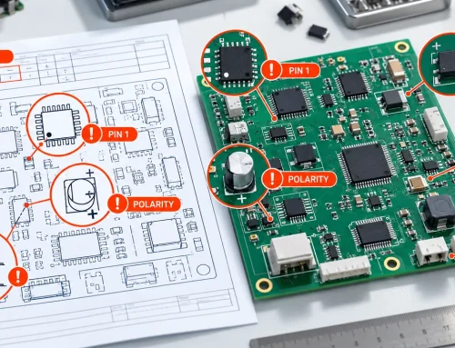
Then identify the proposed configuration with the same precision. A redline or email description is not enough when the change reaches multiple files. Reconcile the schematic, PCB layout outputs, fabrication drawing, stackup, BOM, centroid data, assembly drawing, programming image, test procedure, and mechanical model. The PCB assembly drawing checklist can help prevent a new build from mixing revision, DNP, polarity, and workmanship information.
Create a concise change statement that says what changed, where, why, and which problem or requirement triggered it. Include both intended effects and plausible unintended effects. If the change corrects a failed test, preserve the original failure evidence before rework or redesign.
Classify the change by affected function
Classify by engineering consequence rather than by the number of edited objects. A one-component change can alter safety margin, electromagnetic behavior, thermal stress, startup timing, or regulatory evidence. A large silkscreen cleanup may have no functional test impact but still require documentation and manufacturing-file checks.
Power-path and protection changes
Changes to regulators, FETs, diodes, fuses, current-sense elements, copper width, planes, vias, or protection networks can affect efficiency, thermal rise, current limit, startup, shutdown, transient response, fault energy, and electromagnetic emissions. Revisit worst-case input, load, temperature, and abnormal conditions.
Signal-integrity, clock, or interface changes
Trace rerouting, layer changes, reference-plane discontinuities, termination changes, connector substitutions, and level-shifter updates can affect timing, eye margin, emissions, immunity, interoperability, and cable behavior. A bench functional check at room temperature may not exercise the worst-case interface.
Component alternate or value changes
An alternate MPN can change electrical limits, package geometry, thermal behavior, software timing, qualification status, or assembly process. Use the BOM alternate approval workflow to keep a sourcing candidate separate from an engineering-approved replacement.
Mechanical, connector, or enclosure changes
Mounting holes, board outline, connector location, keepouts, shields, heat sinks, fasteners, and enclosure interfaces affect fit, strain, grounding, airflow, service access, ingress paths, vibration, and drop response. Repeat fit and stress-related checks with production-intent hardware.
Thermal-layout changes
Copper pours, thermal vias, component placement, airflow obstruction, power loss, interface materials, and chassis contact can change component temperature even if the schematic is unchanged. Recheck the actual operating modes and ambient assumptions that drive the thermal result.
Firmware, calibration, or programmable-logic changes
Firmware can change power states, timing, communications, protections, fault recovery, thermal load, and user behavior. Link the software build to the hardware revision and include regression cases for hardware-software interactions.
Build an impact matrix before choosing tests
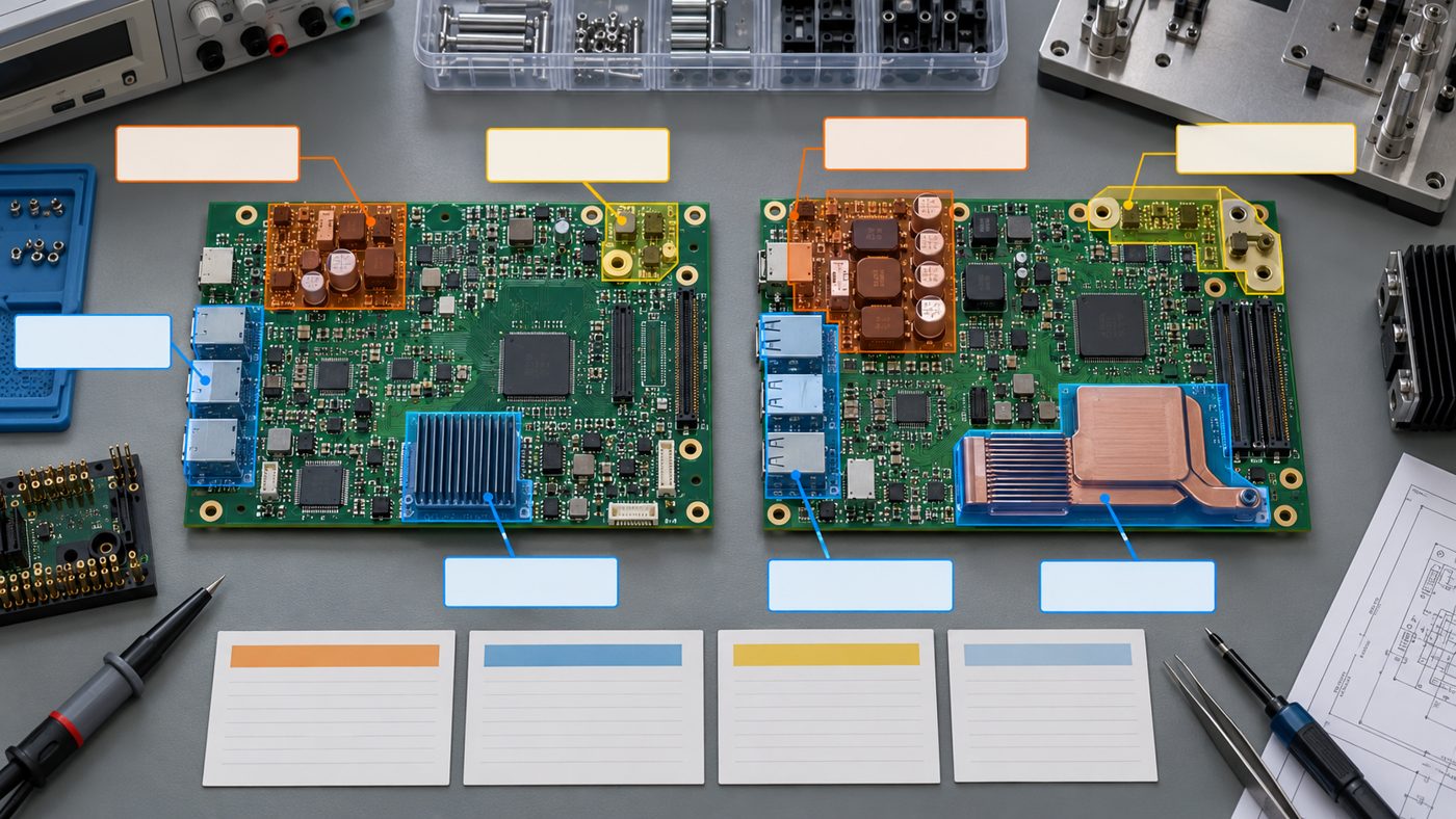
For each change, map the affected item to requirements and prior evidence. A useful impact matrix includes:
| Field | Review question |
|---|---|
| Change identifier | Which approved change request and file revision define it? |
| Affected references or regions | Which components, nets, layers, connectors, mechanical features, or software modules changed? |
| Requirement IDs | Which functional, performance, safety, environmental, interface, and manufacturing requirements may be affected? |
| Failure mechanisms | What new failure, margin loss, or interaction is plausible? |
| Prior evidence | Which report or result supported the baseline requirement? |
| Evidence status | Does it remain valid, require analysis, need a partial repeat, or need a full repeat? |
| Proposed method | Inspection, analysis, demonstration, test, or a justified combination? |
| Samples and conditions | Which builds, quantities, corners, environments, and operating modes are required? |
| Acceptance criteria | What measurable pass condition applies and where is it controlled? |
| Owner and approval | Who executes, reviews, and accepts the result? |
The matrix should also show dependencies. A changed power rail may require electrical margin testing, thermal testing, conducted emissions, startup sequencing, and functional regression. A connector movement may require fit, mating, cable strain, ESD path, signal integrity, and fixture-access review.
Decide whether to inspect, analyze, demonstrate, or test
Not every requirement needs a physical retest. Inspection can confirm an attribute such as drawing conformance. Analysis can show margin when inputs and models remain valid. Demonstration can show an operational capability. Test produces measured evidence under controlled conditions. The selected method should be the one authorized by the requirement and adequate for the change risk.
Reuse earlier evidence only when the tested configuration, interfaces, boundary conditions, and acceptance criteria still represent the revised product. If the original test used a different PCB stackup, component source, firmware behavior, enclosure, cable, or fixture that materially affects the result, the evidence may not transfer.
Document the reason when a test is not repeated. “No impact” should be supported by traceable design comparison, calculations, margins, interface analysis, or other objective evidence. If the reasoning depends on an assumption, state the assumption and confirm it remains true.
When a full test repeat is usually justified
A broad repeat becomes more likely when the change:
- affects a safety, essential-performance, or compliance-related function;
- introduces a new failure mechanism or changes an existing hazard control;
- changes the product’s intended use, operating environment, or external interface;
- invalidates the original test article or boundary conditions;
- alters multiple coupled subsystems and cannot be bounded by analysis;
- modifies the enclosure, grounding, shielding, power architecture, or thermal path used in environmental or EMC testing;
- requires a new manufacturing process whose variation affects product performance;
- changes firmware and hardware together in a way that broadens regression risk.
A full repeat still needs a controlled plan. Define the exact configuration, samples, preconditioning, fixtures, software, test order, environmental conditions, acceptance criteria, and data retention. Do not call a quick bench check a repeat of a formal qualification test.
When a targeted retest can be defensible
A targeted repeat may be appropriate when the changed function and its interactions are well bounded, the applicable requirements are identified, unaffected evidence remains representative, and the residual risk is acceptable to the designated authority. Examples can include a resistor-value correction with clear analytical margins, a relocated test point that does not alter the circuit, or a mechanical label change outside functional interfaces.
Even then, include regression checks around the modified area. Confirm that the correction solves the original issue and does not create adjacent failures. For PCB assemblies, regression may include power rails, current consumption, programming, communications, boundary functions, key analog measurements, fault handling, and manufacturing test coverage.
Choose samples that represent the changed configuration
Use production-intent PCB fabrication, components, assembly process, firmware, enclosure, cables, and thermal interfaces when they affect the conclusion. Track every test unit by serial number or another stable identity. Link it to PCB and assembly revisions, BOM variant, rework history, firmware, and component lots where needed.
A reworked DVT board can be useful for fast diagnosis, but it may not represent a clean production build. Wire patches, hand-replaced components, lifted pads, altered thermal paths, added capacitance, or removed shielding can change the test article. Separate diagnostic evidence from release evidence and plan a clean-build confirmation when risk warrants it.
Sample quantity should reflect expected variation and the purpose of the test. One engineering unit may show that a function works, but it does not characterize manufacturing spread or reliability. Do not invent a universal sample count; use the applicable plan, risk, statistics, customer requirement, and failure consequence.

Coordinate DVT changes with PCB assembly
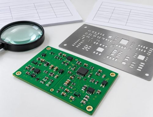
The manufacturer needs a reconciled release package, not only a new Gerber zip. Provide updated fabrication outputs, drill data, stackup and impedance notes, fabrication drawing, BOM, approved alternates, centroid file, assembly drawing, panel and stencil requirements, programming files, test instructions, quantities, and revision notes.
State whether existing boards, components, stencils, fixtures, and work in process can be used, modified, quarantined, or scrapped. Identify any parts that require new sourcing, incoming inspection, moisture handling, programming, X-ray, coating, or special workmanship. The PCB assembly process guide explains where incoming control, paste printing, placement, reflow, inspection, and test can be affected by a change.
Update the test fixture and program relationship when access, net names, limits, connectors, or firmware protocols change. The PCBA testing guide provides context for combining AOI, X-ray, electrical test, programming, and functional verification.
A practical DVT change-review sequence
- Freeze the failure and baseline evidence. Preserve units, logs, photos, measurements, and configuration identities.
- Define the exact change. Reconcile every affected design and manufacturing file.
- Identify requirements and interfaces. Include intended effects and possible side effects.
- Update risk analysis. Add new hazards or failure mechanisms and reassess existing controls.
- Evaluate prior evidence. Mark each result as reusable, supplemented, partially repeated, or replaced.
- Select verification methods. Use inspection, analysis, demonstration, or test with documented rationale.
- Define test articles and conditions. Control hardware, firmware, mechanics, cables, fixtures, and environments.
- Run targeted regression. Confirm the fix and adjacent functions before broader tests.
- Execute required repeats. Follow approved procedures and preserve raw data.
- Review and release. Close deviations, update the matrix, approve the configuration, and transfer consistent files to production.
Common mistakes after a PCB change
- Calling a change minor because only one component or trace moved.
- Repeating only the failed test without checking coupled functions.
- Using a reworked board as the only production-release evidence.
- Testing new hardware with old firmware, fixtures, scripts, or limits.
- Changing the BOM without updating layout, assembly, or procurement records.
- Relying on a full rerun without first confirming configuration and acceptance criteria.
- Declaring prior evidence valid without documenting the boundary conditions.
- Releasing manufacturing files before DVT actions and deviations are resolved.
Frequently asked questions
Does every PCB revision require full DVT again?
No. The scope should follow requirement impact, risk, interfaces, and evidence validity. Some changes justify analysis and targeted regression; others invalidate broad portions of the original qualification. Document the decision and approval basis.
Can analysis replace physical testing?
Sometimes, if the governing requirement allows analysis and the model, inputs, margins, and assumptions remain valid. Analysis should not replace a required test simply because scheduling is difficult.
Can a hand-reworked board be used for DVT?
It can support diagnosis or early verification, but the team should assess whether the rework changes electrical, thermal, mechanical, or manufacturing behavior. A clean production-intent build may still be needed for release evidence.
What should a DVT retest report contain?
Include requirement IDs, change IDs, unit and configuration identity, equipment and fixture versions, procedure revision, conditions, raw data location, results, deviations, conclusions, and approvals.
Who decides the retest scope?
The project’s designated design, quality, regulatory, safety, and verification authorities should decide according to the controlled process. The assembler can provide manufacturing input but should not silently define product acceptance.
Turn the change into traceable evidence
A strong DVT change review does not maximize or minimize testing. It selects enough objective evidence to close affected requirements and risks for the exact released configuration. Freeze the baseline, map the change, assess interactions, preserve valid evidence, repeat what is no longer representative, and record the decision.
For an upcoming revised build, send the schematic, PCB files, fabrication drawing, stackup, controlled BOM, assembly data, firmware, change summary, quantities, and required inspection or functional tests. AssyPCB can review the PCBA release and quote the validation build before materials or tooling are committed.
Latest Blog

Contact Info
Phone: +86-755-82882936
Email: [email protected]
WhatsApp: +86-13570802455
Wechat: +86-13570802455
Address: 2nd floor,D Bldg.,Electric Link Technology Bldg.,Gongming,Guangming New Dist.,518106 Shenzhen, China