
MLCC DC-Bias Checks for Approving BOM Capacitor Alternates
Table of Conent
Table of Conent
An MLCC alternate is not approved just because its nominal capacitance, voltage rating, package code, and dielectric label match the original part. For high-capacitance Class 2 multilayer ceramic capacitors, the useful capacitance in a powered circuit can be much lower than the value measured near zero volts. The amount of loss depends on the exact manufacturer part number, applied DC voltage, temperature, frequency, and construction.
This guide provides a practical worksheet for reviewing MLCC DC-bias behavior during BOM alternate approval. It is intended for hardware engineers, component engineers, buyers, and PCB assemblers who need a traceable decision rather than a distributor cross-reference. If your build needs component sourcing and assembly, AssyPCB can review the BOM and prepare a PCBA quotation when you provide exact part numbers, operating conditions, quantities, and test requirements.
Why nominal capacitance can mislead a BOM review
The value printed in a catalog is measured under defined conditions. It is not automatically the capacitance available at the circuit’s operating voltage. Class 2 ceramic dielectrics such as X5R and X7R provide high nominal capacitance in a small package, but their capacitance can decrease as DC bias is applied. C0G or NP0 Class 1 parts are much more stable with voltage, although they are generally available at lower capacitance for a given size and rating.
TDK and Murata both publish characteristic data showing that DC bias affects high-dielectric-constant MLCCs, and both emphasize using the exact device data. Two parts with the same catalog fields can retain different capacitance because their dielectric formulation, layer thickness, electrode geometry, case size, voltage rating, and product generation differ.
The engineering question is therefore not “Is this a 10 µF, 16 V, X7R, 0805 capacitor?” It is “Does this exact part provide enough effective capacitance at the worst credible operating condition, and does it remain acceptable for the circuit, manufacturing process, and reliability requirement?”
Start with the function, not the candidate part
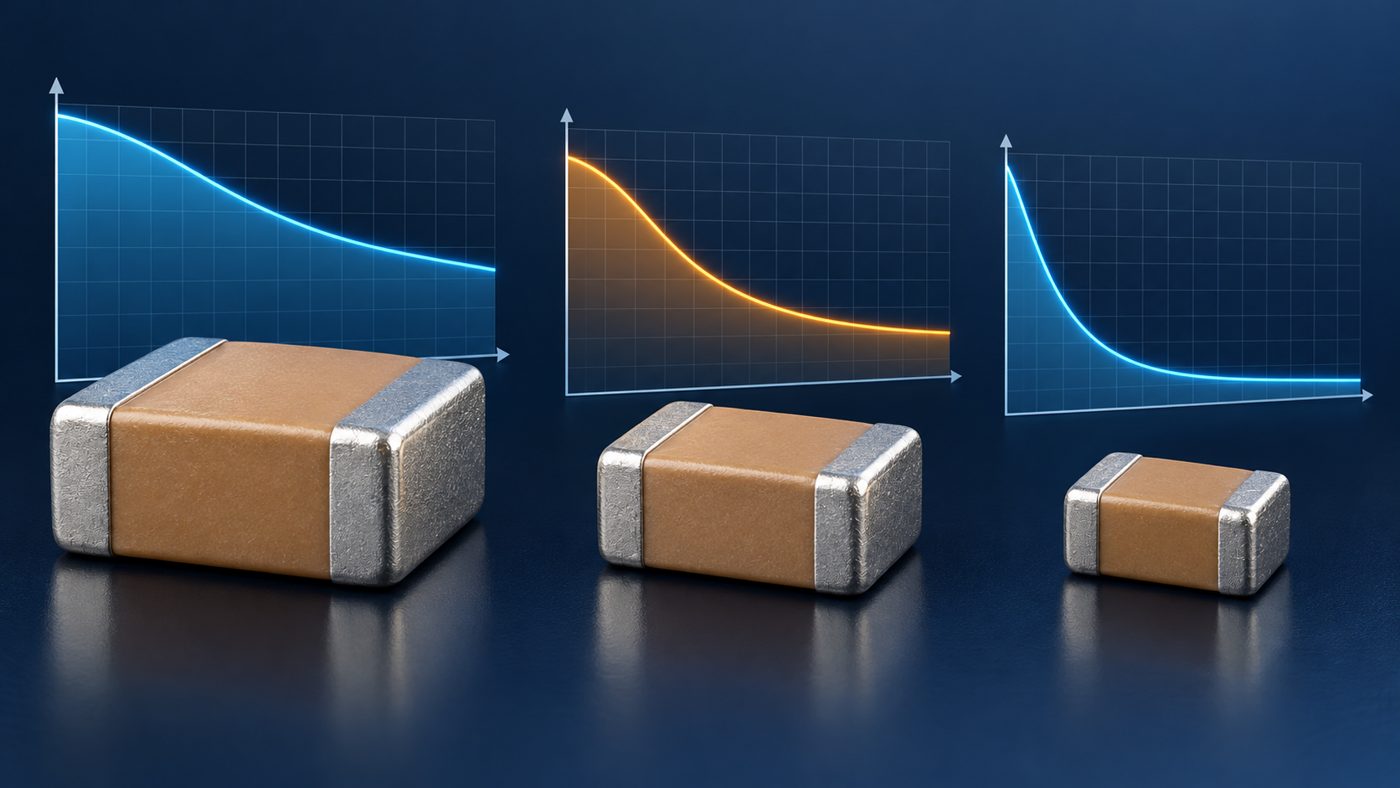
Before comparing alternates, define what the capacitor does. A bulk input capacitor, switching-regulator output capacitor, high-frequency bypass, coupling capacitor, timing element, resonant component, snubber, and safety-related capacitor do not share the same acceptance criteria.
For a regulator output, the control-loop model may depend on minimum capacitance, ESR, and ESL. For a bypass network, impedance over frequency and placement may matter more than the low-frequency nominal value. A timing or filter component may require a stable dielectric and tight tolerance. A snubber may be limited by pulse stress, loss, and self-heating. The application defines which evidence belongs in the approval record.
Record the circuit reference designator, schematic function, normal voltage, maximum steady-state voltage, transient voltage, temperature range, ripple current, frequency range, and minimum acceptable effective capacitance. If the design owner has not defined the minimum, the alternate review has exposed a missing requirement rather than an automatic approval.
Calculate the voltage the MLCC actually sees
Use the voltage across the capacitor, not only the name of the power rail. Include tolerance, startup overshoot, load dump or switching spikes where applicable, and any bias created by the topology. For a capacitor from a rail to ground, this may be close to the rail maximum. For coupling, bootstrap, flying-capacitor, or resonant applications, the stress may require a waveform-based calculation.
Separate the following values in the worksheet:
- nominal rail or signal voltage;
- maximum continuous DC voltage across the capacitor;
- expected repetitive ripple or AC component;
- short-duration transient voltage and duration;
- rated voltage of the original and candidate devices.
A higher rated voltage can improve DC-bias performance in some product families, but that is not a universal rule. A larger case size can also retain more capacitance, yet the exact curves must confirm it. Do not approve a part based on those tendencies alone.
Retrieve part-specific DC-bias data
Use the capacitor manufacturer’s product page, simulation tool, characteristic sheet, SPICE model, or exported curve for the exact manufacturer part number. Generic dielectric charts are educational but insufficient for release control.
Capture the data-source URL, document or tool version where available, access date, measurement conditions, and the curve or table used. If a manufacturer tool allows data export, preserve the file with the component review record. Murata’s SimSurfing and TDK’s component models illustrate the type of part-specific data needed; other manufacturers provide equivalent resources.
If the exact part has no usable bias data, do not silently copy a curve from a nearby family member. Request data from the manufacturer, choose a candidate with documented characteristics, or define a validation test appropriate to the risk.
Build an effective-capacitance worksheet
The worksheet should compare the approved part and every candidate under the same conditions. A useful minimum set of fields is:
| Field | Why it matters |
|---|---|
| Manufacturer part number | Prevents approval of a generic family or distributor description. |
| Nominal capacitance and tolerance | Defines the starting range at the specified measurement condition. |
| Dielectric code | Frames temperature and voltage behavior but does not replace exact data. |
| Case size and height | Affects construction, footprint fit, assembly, and mechanical risk. |
| Rated voltage | Must exceed the defined electrical stress with the required margin. |
| DC-bias curve source | Provides traceable part-specific evidence. |
| Capacitance at maximum DC bias | Shows the effective value at the operating point. |
| Temperature change | Combines with tolerance and bias for the worst-case range. |
| Aging allowance | Accounts for logarithmic capacitance loss in applicable ferroelectric dielectrics. |
| Frequency and AC amplitude | Ensures data matches the circuit and measurement context. |
| ESR, ESL, impedance, and self-resonance | Checks performance beyond low-frequency capacitance. |
| Termination and qualification | Confirms mechanical, automotive, or other program requirements. |
Calculate a conservative minimum effective capacitance using the documented tolerance, DC-bias result, temperature characteristic, and aging assumption. The way these effects combine should follow the manufacturer’s data and the design organization’s method; do not simply add percentages when the source defines a different relationship.
Do not treat X7R as a complete specification
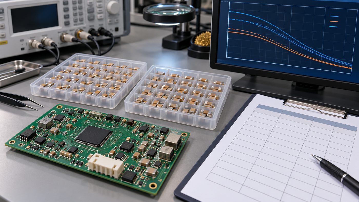
X7R describes a temperature characteristic class over a defined range. It does not guarantee a particular DC-bias curve, ESR, impedance profile, ripple capability, aging rate, mechanical strength, or capacitance at the application voltage. X5R and X7R labels are useful screening fields, but they are not interchangeable approvals.
The same warning applies to package size and voltage rating. An 0603 device can have a different internal construction from an 0805 device of the same nominal value. Two 16 V parts can retain different capacitance at 5 V. A smaller replacement may fit the pads poorly or increase flex-cracking sensitivity even if the electrical model passes.
For a broader controlled-substitution workflow, use the BOM alternate approval guide. It separates sourcing suggestions from engineering authority and release scope.
Check the circuit consequences
Switching-regulator stability and transient response
Many regulators specify a minimum output capacitance and an acceptable ESR range. Use the IC vendor’s current datasheet and design tools. The effective capacitance should meet the requirement over bias, tolerance, temperature, and aging. A candidate with lower effective capacitance can increase ripple, worsen load transients, or move the control loop outside the qualified region.
Input decoupling and ripple current
Input capacitors conduct pulsed current and must be placed close to the switching path. Review RMS ripple, self-heating, impedance, voltage stress, and parallel-part current sharing. Nominal capacitance alone does not prove that a smaller substitute is suitable.
Timing, sensing, and analog filters
Voltage-dependent capacitance can shift a pole, time constant, gain, or linearity. Stable Class 1 dielectric or another capacitor technology may be more appropriate when capacitance accuracy matters. Evaluate dielectric absorption, microphonics, leakage, and distortion where the circuit is sensitive.
Resonant and snubber networks
Check pulse voltage, dV/dt, loss, self-heating, frequency behavior, and component-specific application guidance. A high nominal value with poor effective behavior may not deliver the intended energy storage or impedance.
Confirm mechanical and assembly compatibility
Electrical approval is only half of the decision. Compare length, width, height, land-pattern compatibility, termination material, plating, reflow limits, moisture or handling requirements where applicable, and packaging format. A different case height can conflict with an enclosure, shielding can, or automated optical inspection view.
MLCCs are brittle. Board flex during depanelization, connector insertion, screw fastening, or enclosure assembly can crack the ceramic. Review component orientation relative to board bending, distance from routed edges, pad geometry, and whether a soft-termination or other mechanically robust series is required. The component packaging guide also explains why reels, cut tape, trays, and traceability affect line readiness.
For a PCBA release, keep the alternate’s exact MPN, manufacturer, lifecycle status, authorized source, packaging suffix, and approved scope in the controlled BOM. The PCB assembly variants guide shows how BOM and population control should stay aligned with the correct assembly revision.
Validate the candidate at the right level
Documentation may be enough for a low-risk bypass capacitor with comfortable margin. Higher-risk substitutions may need simulation, bench testing, prototype assembly, thermal measurement, ripple and transient checks, startup and shutdown testing, environmental testing, or qualification to a customer-controlled plan.
Use production-intent boards and operating modes. Measure the circuit outcome that matters rather than trying to infer installed capacitance from a handheld meter alone. A regulator alternate review may include output ripple, load-step response, loop stability evidence, capacitor temperature rise, and behavior across input voltage and ambient temperature.
A practical approval workflow
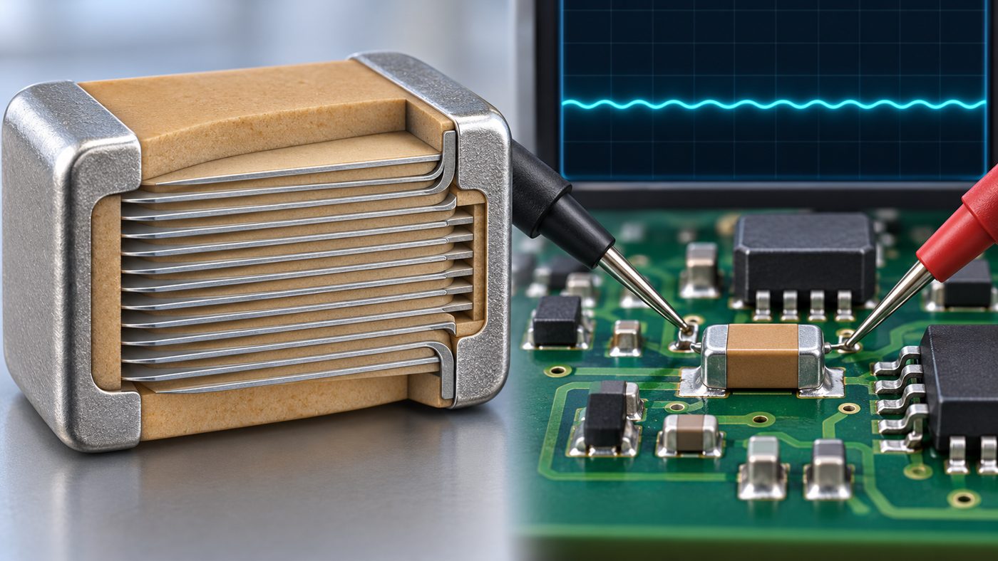
- Identify the approved part and application. Record the exact MPN, reference designators, circuit function, and release revision.
- Define operating stress. Document DC voltage, transients, ripple, frequency, temperature, and mechanical conditions.
- Set acceptance limits. State minimum effective capacitance and any ESR, impedance, height, qualification, or sourcing constraints.
- Collect exact candidate data. Preserve datasheets, curves, models, product status, and source evidence.
- Calculate worst-case performance. Include tolerance, bias, temperature, aging, and relevant frequency behavior.
- Review PCB and assembly fit. Check footprint, case dimensions, height, termination, packaging, and flex risk.
- Plan verification. Use analysis, simulation, bench tests, or pilot builds proportional to the failure consequence.
- Approve with scope. State product, PCB revision, reference designators, quantity or lifecycle scope, and required controls.
- Release and communicate. Update the controlled BOM, purchasing system, work instructions, and test plan before parts reach the line.
Common MLCC alternate mistakes
- Comparing only capacitance, rated voltage, package, and X7R/X5R code.
- Using a generic family chart instead of the exact part-number curve.
- Evaluating the nominal rail while ignoring tolerance and overshoot.
- Assuming a higher voltage rating always guarantees better capacitance retention.
- Ignoring aging, temperature, frequency, ESR, ESL, and self-resonance.
- Approving a smaller case without checking pad fit and board-flex risk.
- Accepting a distributor suggestion without design-owner approval.
- Changing the BOM without updating the assembly revision and verification record.
Frequently asked questions
Does an X7R capacitor keep its nominal capacitance at rated voltage?
Not necessarily. X7R identifies a temperature-characteristic class, not guaranteed capacitance retention under DC bias. Use the exact manufacturer part-number data at the intended voltage.
Can a higher-voltage MLCC replace a lower-voltage part?
It may be a useful candidate, but it still requires part-specific electrical and mechanical review. Higher voltage rating does not by itself guarantee the required effective capacitance, impedance, footprint fit, or qualification.
How should DC-bias loss be written in a BOM?
Keep the BOM tied to approved manufacturer part numbers. Put the minimum effective-capacitance requirement and evaluation conditions in the engineering specification or controlled approval record, then list only candidates that have passed that requirement.
Is a capacitance meter enough to approve an alternate?
No. A basic meter may test near zero DC bias and at a frequency that does not represent the application. Use manufacturer data and circuit-level verification matched to the actual operating conditions.
When is a pilot build appropriate?
Use a pilot when the substitution has meaningful electrical, thermal, mechanical, sourcing, or qualification risk that documentation and simulation cannot close. The test plan should measure the product behavior the capacitor influences.
Turn the curve into a controlled decision
An MLCC DC-bias curve is not a minor datasheet detail. It can determine whether a power rail has enough output capacitance, whether a filter meets its target, or whether a nominally equivalent BOM substitute changes product behavior. Start with the circuit requirement, use exact part data, calculate the worst-case effective value, review assembly fit, and release the alternate with clear scope.
For a sourcing and manufacturing review, provide Gerber or ODB++ data, the controlled BOM, approved and candidate MPNs, operating voltages, quantities, target schedule, and test expectations. AssyPCB can quote PCB assembly and review component-alternate risks before procurement or production release.
Latest Blog

Contact Info
Phone: +86-755-82882936
Email: [email protected]
WhatsApp: +86-13570802455
Wechat: +86-13570802455
Address: 2nd floor,D Bldg.,Electric Link Technology Bldg.,Gongming,Guangming New Dist.,518106 Shenzhen, China