
Conformal Coating for PCBAs: Specify Exposure and Acceptance
Table of Conent
Table of Conent
Choose a conformal coating from the assembly’s real exposure and service plan, then specify how it will be applied and accepted. A resin family alone cannot tell a supplier which connectors must remain clean, whether the board may be repaired, or what evidence shows that a production assembly is protected. Start with the enclosure and failure risk: condensation, chemical splash, conductive contamination, and temperature cycling pose different questions. Shortlist materials against those conditions, then release one drawing that defines coverage, keep-outs, material, cure, inspection, and test ownership.
What exposure must the finished assembly survive?
Describe the environment at the board, not just the product category. An indoor controller in a cabinet may see condensation during shutdown. A washdown device may encounter cleaning chemicals if liquid crosses an enclosure boundary. A serviceable outdoor unit may need connector access after years in the field. State the liquid or vapor, temperature and humidity cycle, powered or unpowered condition, contamination source, and expected service life. Include known ingress paths. Coating cannot correct an enclosure that directs liquid onto a connector or replace adequate electrical spacing.
IPC’s conformal coating handbook organizes selection around end-use environment, material, application, inspection, and repair. Its scope assigns users responsibility for establishing suitability through appropriate testing. Use that as a decision sequence, not proof that any coated board meets a humidity or chemical rating. The environmental test selection guide helps separate field risks from chamber test names; a passing material coupon and a passing populated assembly answer different questions.
Record the failure mode before choosing chemistry. Is the concern leakage across contaminated conductors, corrosion at an exposed contact, material swelling, intermittent sensor readings, or a field repair that disturbs the film? This keeps the coating specification tied to a measurable outcome. It also exposes cases where cleaning, sealing, drainage, or a mechanical change needs attention before adding a coating step.
Use material families to shortlist, then qualify a product
Acrylic is often considered when application and later rework matter. Urethane formulations are often evaluated for chemical resistance; silicone formulations are often evaluated for flexibility and thermal cycling. These are screening tendencies, not guarantees. Supplier formulations within one family differ in solvents, cure, viscosity, thickness, adhesion, rework method, and component compatibility. Request the exact product technical data sheet and test representative hardware with the intended process.
Manufacturer HumiSeal selection guidance couples chemistry with throughput and application control. It is useful for a shortlist; product data and customer qualification should settle a purchase specification. If a supplier cites IPC-CC-830 qualification, check its scope: IPC-CC-830C checks coating material properties on standardized test vehicles. It does not prove coverage, adhesion, cleanliness, or electrical performance on your populated board.
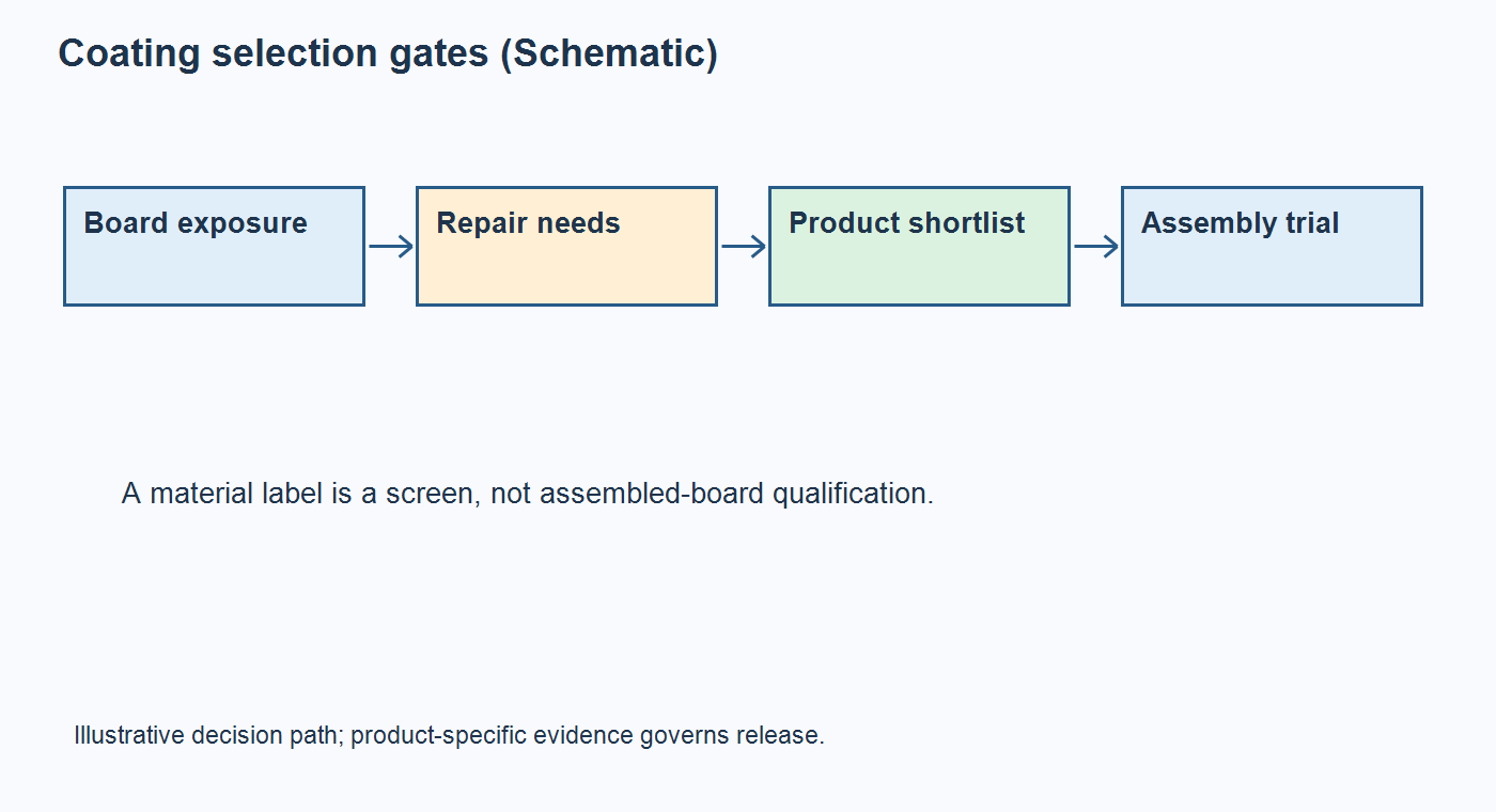
Do not copy a standard thickness from another product without checking the chosen material and application method. NASA-STD-8739.1B gives different cured-thickness ranges by coating type for NASA mission hardware. Those values show why one universal thickness is misleading; they are not an automatic commercial-PCBA limit. Agree a target and tolerance with the material supplier and assembler, then define how the cured film will be measured without damaging production boards.
Which surfaces need coating, and which must stay bare?
Make the assembly drawing unambiguous. Show top and bottom coverage, edge treatment, connector and socket mating surfaces, switches, test points, fasteners, grounding locations, heatsink contact areas, and adjustable devices. Define a boundary tolerance where overspray or flow could interfere with function. A shaded polygon alone may be insufficient at tall parts: state whether the underside, lead exit, or vertical wall needs coverage. Review whether coating can wick into a connector or become trapped under a part that must be replaced.
NASA’s polymeric-application workmanship standard defines keep-out areas and masking and requires specified coverage and post-cure examination for its mission hardware. The transferable principle for a commercial drawing is an explicit boundary and evidence, not an unsupported claim of NASA compliance. The assembly drawing checklist helps align the coating view with the BOM, connectors, hardware, and board revision.
Ask the assembler to review geometry against the proposed method: selective machine, spray, dip, brush, or a combination. Spray may need masks and fixture control. Dip can reach under some components but may deposit material where mating surfaces must remain bare. Selective equipment needs access paths and stable edge behavior. HumiSeal’s selective-coating process guidance identifies material flow, valve choice, fixturing, and inspection timing as practical controls. A low material price can lose its advantage through extensive masking or rework.
If the material is plausible but the coating boundary is still uncertain, share the assembly drawing and exposure brief for a scoped review with the BOM, board quantity, proposed keep-outs, and service requirements. Ask which masking, application, and test assumptions need an engineering decision before a comparable PCBA price can be prepared.
Specify process and acceptance evidence together
Name the approved manufacturer and grade, or define an approved-substitution route. State surface preparation and cleanliness, application method if design-critical, cure schedule or approved process window, cured film target, and inspection method. Coordinate coating with assembly operations that must remain visible or testable. Confirm whether functional testing happens before coating, after coating, or both, and what a failed unit’s rework path looks like.
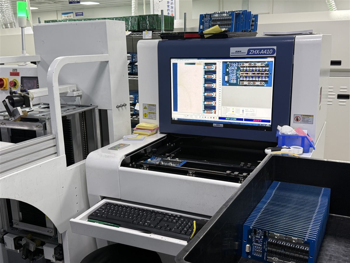
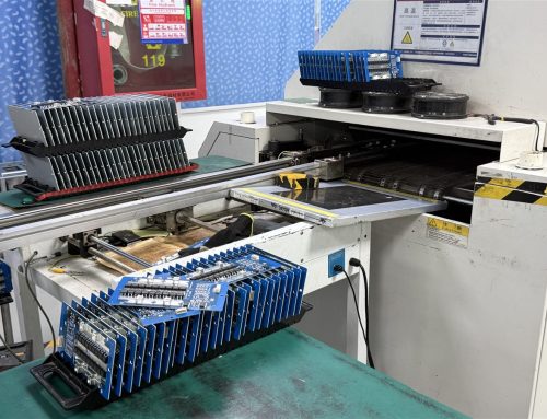
Optical inspection of solder joints before coating and fluorescence inspection of coating coverage answer different questions. UV images can show fluorescent tracer location but cannot independently prove cure, adhesion, ionic cleanliness, or environmental durability. A cured-film witness coupon can support thickness measurement where direct probing risks damage. NASA’s program-specific standard provides examples of distinct pre-cure, cure, post-cure, keep-out, and thickness checks; choose the checks appropriate to the actual product specification. The real factory AOI station below represents an earlier assembly-inspection step, not a coating inspection record.
| Assembly risk | Specification input | Evidence to request | Open decision before RFQ |
|---|---|---|---|
| Condensation or polluted humidity | Board-level exposure cycle, powered state, cleaning baseline, coverage map | Material data and representative assembly exposure with post-test electrical criteria | Which nodes and enclosure interfaces set the limit? |
| Chemical splash or cleaning agent | Actual fluid, contact duration and temperature, ingress path | Material compatibility evidence and product-level sample check | Is sealing or drainage needed first? |
| Connector, test-point, or ground contamination | Dimensioned keep-outs, boundary tolerance, process route | Post-cure visual or agreed UV coverage record and mating check | Who owns masking and out-of-zone rework? |
| Long cure or field repair | Cure window, component thermal limit, removal method | Cure record and repair trial on representative hardware | Does the quoted cycle include cure and reinspection? |
Use the table to compare quotations on a common scope. Evidence should be proportional to product risk and contract requirements; do not request a test simply because it appears in a handbook. Define the acceptance condition, sample size, responsible party, and revision for qualification. A material certificate, process record, and finished-assembly test have different roles. Ask which records are routinely available and which require a separately quoted validation plan.
What changes in the PCBA quote?
Coating cost exceeds resin consumption. Compare cleaning and drying, masks and fixtures, dispensing or spray programming, operator time, cure capacity, inspection, test sequencing, scrap and rework rules, and packaging after cure. Include the effect of a second side or a connector that needs precise masking. HumiSeal’s masking and rework discussion highlights those process costs; vendor-specific savings figures should not be imported into a new RFQ. The food-line detector coating-versus-potting example presents a narrower application choice; this specification framework applies before quoting any defined exposure.
Include the assembly drawing, BOM, quantity, target material or candidate list, keep-outs, cleaning requirement, cure constraint, inspection and electrical acceptance, and expected repair method in each RFQ. Ask suppliers to state assumptions so a low price does not simply omit cleaning, masking, or validation.
Release one controlled coating package
Keep the coating drawing on the same revision as the board, BOM, assembly view, and test plan. Record approved substitutions and the review trigger for a new coating, altered solvent, cleaning chemistry, or application method. A change that looks equivalent on a data sheet can alter wetting at keep-outs, cure time, adhesion, or repair. The full turnkey assembly scope is a starting point for coordinating fabrication, sourcing, assembly, and testing; the exact coating process and acceptance records still need to be specified in the RFQ.
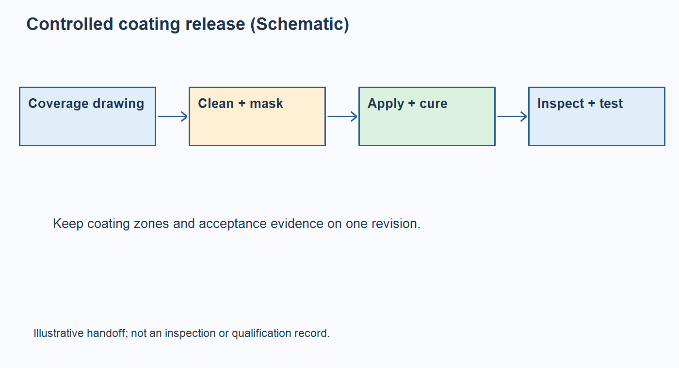
A ready-to-quote package answers four questions: what exposure matters, exactly where coating belongs, what material and process are approved, and how success will be checked on the finished assembly. If one answer is missing, treat the material choice as provisional. Once those boundaries are defined, send the controlled coating package for review with the drawing, quantity, acceptance plan, and qualification-test owner. This makes the decision reviewable before production rather than discoverable only after rework.
Latest Blog
Contact Info
Phone: +86-755-82882936
Email: [email protected]
WhatsApp: +86-13570802455
Wechat: +86-13570802455
Address: 2nd floor,D Bldg.,Electric Link Technology Bldg.,Gongming,Guangming New Dist.,518106 Shenzhen, China