
Baggage Handling Controller PCB Cost: Connectors, Terminals, and Variants
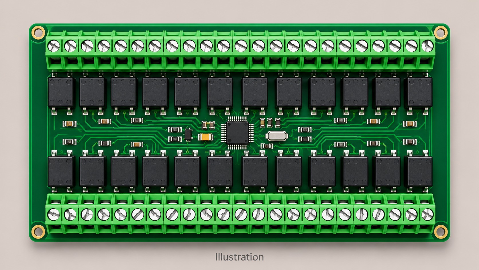
Table of Conent
Table of Conent
Baggage handling controller PCB cost should be compared against the connector configuration, soldering route, actual release quantity, and accepted test coverage. A board with many field-wiring terminals can carry substantial work in insertion, support, soldering, inspection, and test connections. The balance depends on the exact design and supplier process. Start with a joint map and a variant-by-release schedule, then ask each bidder to separate recurring build charges from tooling, programming, fixtures, and engineering work.
A lower component price becomes a useful saving when the proposed part preserves the installed interface and the approved manufacturing requirements. Likewise, a shared bare PCB can reduce purchasing complexity while still needing separate population files and tests. Use the same bill of materials, mechanical constraints, workmanship requirements, coating scope, and functional acceptance criteria in every comparison. This gives engineering and procurement a way to identify which changes reduce delivered cost and which ones simply move work into harness assembly, commissioning, or future production releases.
Define the controller and the quoted release
Define the controller’s system boundary and the quantity released for manufacture before comparing unit prices. This article concerns airport baggage conveyors and related ground material-handling electronics. A zone controller may connect sensors, motor drives, neighboring zones, and a supervisory network. Interroll’s conveyor control overview describes controls that coordinate RollerDrive equipment, sensors, speed, direction, and accumulation logic. The installation determines the functions and interfaces your own board needs.
Record whether the supplier delivers a bare PCBA, a programmed board, an enclosed controller, or a module with mating plugs and harnesses. Include the power and I/O configuration, board outline, mounting arrangement, expected environment, and responsibility for equipment-level verification. A quote for a board alone can look attractive beside a quote that includes programming, a mating connector kit, functional testing, and labeling. Align those deliverables first.
Provide both the forecast and the purchase-release schedule. An annual total can help with component purchasing, but the actual batch still needs setup, material verification, and the correct configuration files. Request separate entries for board fabrication, parts, assembly, programming, recurring inspection and test, one-time work, and any excluded items. Ask which charges recur at another release and which remain valid while the configuration stays unchanged.
Map the connectors to the assembly route
Use the exact part numbers and joint locations to choose a feasible soldering route. Count connector positions, electrical solder joints, mechanical retention features, insertion operations, and parts requiring secondary attachment. A connector body with many positions creates a different process problem from many separate single-position devices. Show which joints contact large copper areas, which are near underside components, and where supports or enclosures limit access.
Through-hole pins can sometimes be assembled within reflow. Phoenix Contact’s SMT connector guide explains through-hole reflow, also called pin-in-paste, and the component and processing requirements involved. Review the connector’s thermal suitability, packaging, pickup arrangement, paste delivery, hole and lead geometry, and inspection method. Through-hole construction alone does not establish whether a separate soldering operation is required.
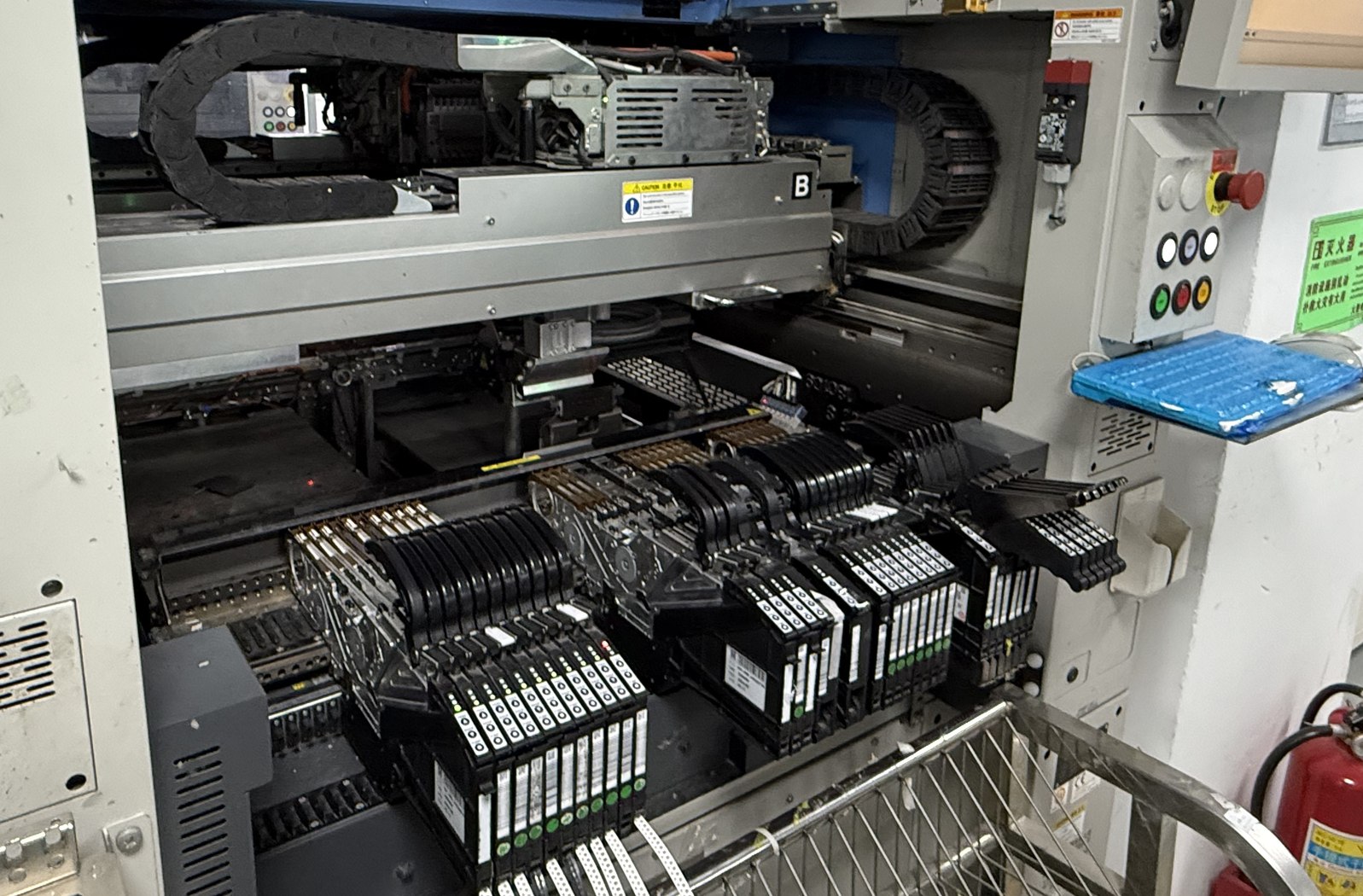
For a selective-solder proposal, review access to the actual joints and the effect of nearby components. Ersa’s selective-solder nozzle guidance identifies dense layouts and restricted access as process considerations. Ask the assembler to mark any joint needing a different nozzle, carrier, manual operation, or special thermal review. The selective soldering joint-map review gives a framework for recording those exceptions before pricing them.
For a route and batch review, share the variant matrix and connector joint map with the quantities, fitted options, and proposed soldering route. The review can identify what setup is reusable, what needs separate verification, and which assumptions belong in the assembly price. Compare savings over the releases you actually expect to order, including smaller service builds where those are part of the product plan.
| Proposal | Verify before accepting | Cost boundary to compare |
|---|---|---|
| Keep terminals and selective-solder them | Joint access, thermal demands, support, inspection and permitted touch-up | Programming, carrier or tooling, recurring cycle and secondary work |
| Use a reflow-compatible through-hole alternative | Approved mating fit, thermal rating, packaging and solder-process feasibility | Part and placement cost against any operation removed |
| Use an SMT-compatible connector | Footprint, retention, loading, mating duty and approved process | Assembly changes plus mechanical reinforcement or redesign |
| Move terminations to a separate harness | Mating scheme, wire preparation, access and field service method | PCBA, harness manufacture, connector kits and commissioning work together |
Quote the panel arrangement and handling requirements alongside the assembly. Connector overhang, tall parts, support points, and depanelization access can affect both the workable array and the assembly sequence. Ask which panel rails or supports the assembler needs and whether the proposed carrier fits every option. Record any change to the bare-board array before comparing fabrication prices, since a different panel quantity or routing arrangement can change both material utilization and the operations being priced.
Price each released variant as its own configuration
A common bare board can support several products, while each populated option still needs a controlled build identity. Create a matrix containing assembly number, revision, quantity per release, fitted and do-not-populate positions, firmware or configuration identifier, connector options, label, and test program. The PCB assembly variant release guide describes how population decisions should remain consistent across the BOM, placement data, and assembly drawing.
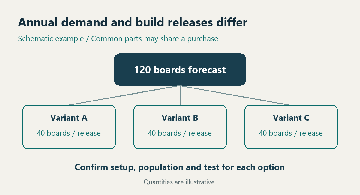
For example, a forecast of 120 boards divided among three 40-board options does not establish a 120-board identical build. Purchasing may aggregate common parts. The assembler must still verify each option, load the right files, and establish its first acceptable unit. Some stencil, fixture, or program elements may be reusable. Ask the supplier to identify those shared elements and the configuration-specific effort explicitly.
Compare test investment over the builds it will cover
Compare test routes using the additional investment and the units that the route demonstrably covers. A simple screening calculation is incremental one-time cost divided by positive per-board recurring savings. It estimates a break-even quantity only when coverage, accepted quality, release mix, and other obligations are comparable. If a proposed route adds maintenance, changeover, adapters, retest, or software support, include those costs over the same planning period.
| Cost or coverage item | Evidence to request | Decision |
|---|---|---|
| Base fixture and adapters | Supported board revisions, connector access and options requiring another adapter | Allocate only genuinely shared hardware across the covered builds. |
| Functional sequences | Input stimulation, output loading, acceptance limits and configuration selection | Budget option-specific programming and verification. |
| Recurring execution | Loading, connections, programming, test, records and unloading scope | Compare the complete cycle under the same pass criteria. |
| Changes and upkeep | Maintenance ownership, software retention, adapter replacement and change triggers | Include continuing support in the total-cost comparison. |
For a conveyor controller, specify which sensor inputs are simulated, how outputs or drive interfaces are exercised, and what network behavior is checked. Define a representative load where required by the design. A successful power-on does not exercise every channel. Preserve the assembly identifier and test version in the record so a future option change can be assessed against the actual coverage.
Evaluate cost reductions against the installed interface
Approve connector and BOM changes against electrical, mechanical, service, and manufacturing requirements together. Compare the complete mating system, wire range and termination method, pitch, current and voltage conditions, mounting, retention, and accessibility. TE’s PCB terminal-block product information illustrates the product-specific fields available for a through-hole header. Use the selected part’s drawings and application information to review the full interface and soldering requirements.
OrinewPCB’s video discusses BOM cost reduction after product finalization. Use it as context for a controlled review of sourcing and component choices, while retaining the approval steps and evidence required for this controller.
For every proposed saving, record the original configuration, the proposed change, its owner, and the verification needed before use. Ask whether the change affects the harness, enclosure, test adapter, documentation, or installed spares. The purchasing comparison should include any engineering and validation work needed to release it. Keep coating, cleanliness, inspection class, and acceptance requirements tied to the actual environment and customer specification.
Release one comparable fabrication and assembly package
A comparable quotation needs one released configuration, an explicit delivery boundary, and an itemized set of recurring and one-time obligations. Reconcile the connector route, variant matrix, planned releases, and test coverage before selecting a proposal. A full-turnkey PCB assembly scope can coordinate fabrication, parts sourcing, assembly, and agreed testing around that same package. Specify which records arrive with each build and who approves deviations.
For a controller ready for manufacturing review, send the released board and assembly files together with the BOM and approved alternates, placement data, assembly drawing, quantities by option and release, programming ownership, and test requirements. Include mating or harness drawings where the proposed interface affects them. That package lets the review clarify manufacturing assumptions and quotation scope before a cost reduction is accepted for production.
Latest Blog




Contact Info
Phone: +86-755-82882936
Email: [email protected]
WhatsApp: +86-13570802455
Wechat: +86-13570802455
Address: 2nd floor,D Bldg.,Electric Link Technology Bldg.,Gongming,Guangming New Dist.,518106 Shenzhen, China
