
Mud-Pulse Telemetry PCB: Select Nets for Impedance Control

Table of Conent
Table of Conent
Impedance control on a mud-pulse telemetry PCB belongs to specific electrical interconnects, not automatically to the slow pressure pulses traveling through drilling fluid. Start with the actual circuit: identify the driver, receiver, transition time or analog bandwidth, route and connector length, reference path, and operating conditions. A fast clock or a long module link may need a controlled transmission-line structure; a short local sensor or ADC connection may need noise and loading control instead. The OEM must set any impedance target and tolerance for named nets, and the fabricator must return a buildable stackup and measurement plan. Neither a coupon result nor a functioning telemetry link establishes intrinsic-safety approval. This guide gives engineering and procurement teams a conditional net-selection worksheet and three separate release records. It assumes no particular downhole tool layout, temperature rating, circuit classification, or certification status.
Separate the mud-pressure channel from electrical routes
The telemetry medium and the PCB interconnect are different physical systems. Mud-pulse telemetry sends downhole measurements toward the surface as pressure variations in the mud system, as the SLB mud-pulse glossary explains. Its pressure modulation rate does not define the characteristic impedance of a copper trace inside the electronics package. Conversely, an internal digital edge can be fast even when the information ultimately travels through the mud at a much lower symbol rate.
Map the actual architecture before specifying a board. A sensor interface, converter, processing device, actuator driver, board-to-board link, harness, and surface receiver can have different electrical requirements. The existence and placement of those blocks are design inputs, not facts about every mud-pulse tool. The original equipment manufacturer (OEM) should identify which part of the link this PCB implements and provide the applicable schematic, interconnect drawing, and test boundary. The intrinsically safe telemetry PCBA handoff addresses the related configuration and cable-approval responsibilities; this article narrows the question to selecting impedance-controlled nets.
A buying note that says only “controlled impedance on telemetry board” is not executable. It leaves the fabricator to guess whether the concern is a digital transmission line, an analog input, a cable, or a pressure-wave phenomenon outside the PCB. That ambiguity can add unneeded coupon work while still missing the interface that actually needs electrical validation.
Rank the electrical paths before setting a target
Screen each candidate net by electrical edge and interconnect delay, then assign a physical structure and owner-approved acceptance method. Altium’s controlled-impedance guidance uses edge time relative to route delay as a way to identify possible reflection problems and explains why conductor geometry, dielectric, and a continuous reference path affect impedance. Its one-third-rise-time screen is a design prompt, not a universal release limit for an unknown tool.
For a digital path, obtain the source output behavior or model, receiver requirements, estimated routed length, layer transitions, connector or cable segments, and allowed termination strategy. The engineer decides whether simulation or measurement shows a transmission-line issue and specifies the target and tolerance where needed. A named differential pair is not automatically a standard value; its required geometry depends on the actual interface and stackup. For a slower control net, a sensible return path and electromagnetic compatibility still matter even if no impedance coupon is justified.
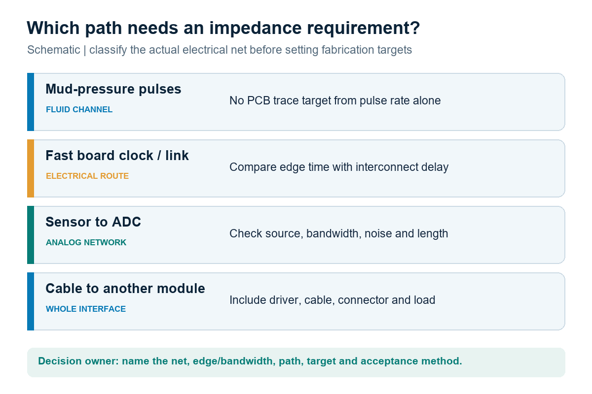
| Path being reviewed | What the design owner must determine | What purchasing or fabrication should request |
|---|---|---|
| Mud-pressure telemetry medium | Fluid-channel performance and pulser/system requirements, outside PCB trace geometry | No PCB impedance target derived solely from pressure-pulse rate |
| Fast on-board digital clock or data link | Edge time, route delay, driver/receiver models, return path, permitted termination | Named net class, layer, target/tolerance if justified, stackup and coupon scope |
| Sensor-to-converter analog path | Signal bandwidth, source and input loading, noise and route length | Layout and test requirements; controlled impedance only when the actual network warrants it |
| Intermodule electrical connection | Driver, board route, connector, cable, receiver, and environment as one path | Defined interface test plus any board-only impedance class, with separate owners |
This is a decision framework, not a claim that the pictured or quoted circuit exists in a specific tool. A PCB-only impedance target cannot repair an unmatched connector or cable. Likewise, a digital waveform that performs on one prototype does not release a different production stackup without review.
Treat the sensor and ADC path on its own terms
Do not label every analog route a controlled-impedance transmission line. For a low-bandwidth sensor network, source impedance, biasing, input filtering, return-current placement, shielding, leakage, and noise can dominate the board decision. In a higher-bandwidth case, a long incoming connection can require matching. Analog Devices’ ADC-driver note makes that distinction in its high-speed example: the longer input connection may need a controlled line, while a closely placed driver-to-ADC connection may not. That example does not establish what is on the OEM’s mud-pulse board.
Ask the design owner for the sensor type, source network, usable signal bandwidth, input circuit, accepted noise or error budget, and representative harness length. On the layout, inspect the actual return-current route and whether digital switching or an actuator path crosses a sensitive analog region. If a high-speed input or intermodule connection needs a controlled structure, state where the line begins and ends; do not extend a PCB coupon claim across a connector or cable that it does not contain.
When the net classes and sensor interface are still open, the controlled-net list and electrical schematic are useful inputs for a manufacturing review. An OEM can share the candidate nets and stackup for review with the schematic, target quantity and intended assembly scope so OrinewPCB can identify fabrication and assembly assumptions before pricing the build. The OEM remains responsible for setting performance limits and any protection-related design approvals.
Specify a fabrication model and measurement window
A controlled net becomes a fabricable requirement only when the released geometry, material assumptions, adjustment authority, and measurement method agree. Give the board supplier the signal layer, reference plane, line type, target and tolerance approved by the OEM, and any locked width or spacing. Ask for the proposed production stackup rather than treating the design-stage dielectric number as a guaranteed finished-board result. The existing impedance-controlled PCB RFQ guide covers the complete bid package and ordinary coupon deliverables.
Before using a TDR coupon as acceptance evidence, match its layer, dielectric, copper and mask state to the class it represents, and define the probe launch and reading interval. Polar’s short-trace TDR note shows how launch ringing and the choice of a flat measurement region can complicate very short structures. It does not supply a universal coupon length or acceptance window for this design. Record the coupon design, lot or panel identity, agreed method, measured trace or value, tolerance, and disposition.
A standard impedance note cannot replace a controlled revision. Capture any CAM proposal to change trace width, pair gap, dielectric or laminate as an exception for the named design owner. If a board will operate outside the conditions used for the impedance model, request the relevant material properties and system validation from the OEM. Do not assume that “downhole” implies a particular temperature, that ordinary FR-4 is qualified or disqualified for every assembly, or that a room-temperature coupon alone proves field behavior.
OrinewPCB’s short video below illustrates why a simulated differential target and a measured TDR result may differ when pads, stubs, probe access, and coupon design change the measurement. It is AI-generated explanatory material, not footage of this mud-pulse PCB or a production test record.
Keep intrinsic-safety changes in the approval lane
Controlled impedance and intrinsic safety answer different questions. The public scope of IEC 60079-11:2023, corrected in July 2026, concerns construction and testing of intrinsically safe and associated apparatus. That scope does not certify a PCB, a supplier, or a mud-pulse system. Whether a particular tool falls under an intrinsic-safety assessment, and which protection configuration applies, must come from the responsible product owner and its applicable approval documents.
A proposed trace, laminate, spacing, component, cable or manufacturing-site change can affect both electrical performance and an assessed configuration. Send the change to the named electrical authority and, where required by the applicable approval route, to the responsible protection assessor. A coupon pass answers whether an agreed fabricated structure met its measurement rule; it does not authorize a different energy-limiting circuit or connector. A telemetry function test answers whether the chosen interface works under its defined conditions; it does not substitute for the protection record.
For a controlled release, keep a revision index spanning the schematic, fabrication data, stackup, BOM and approved alternates, assembly drawing, firmware, cable or module interface, and test procedure. Specify which documents the EMS receives and which deviations must stop production pending owner disposition. The general OrinewPCB service description can support a coordinated fabrication, sourcing, assembly and test-scope discussion, but it is not evidence of a project-specific intrinsic-safety certification.
Release fabrication, interface and protection evidence separately
Use three linked records at pilot release: one for what the fabricator built, one for what the assembled electrical path did, and one for the product’s assessed configuration. Polar’s transmission-line configuration note explains the role of trace geometry, dielectric and reference planes in the first record. The other two records depend on the actual equipment interface and approval route. Joining all three by design revision and build lot makes their limits visible rather than allowing a single “pass” stamp to stand for the whole product.
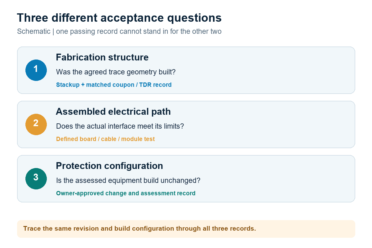
| Release question | Useful record | What the record does not prove |
|---|---|---|
| Was the selected structure fabricated? | Released stackup and net class, agreed coupon/TDR method, lot-linked result and exceptions | Performance through all packages, connectors, cables or operating conditions |
| Did the complete electrical interface work? | Named board and module revisions, representative load and cable, procedure, limits and measured functional result | That every fabricated impedance class passed or that a protection configuration is approved |
| Is the delivered protection configuration authorized? | Owner-controlled baseline, change disposition and applicable assessment or certification evidence | Automatic electrical performance of an untested new route or module |
Request that the supplier return exceptions before substituting material or editing CAM data. The engineer should state which impedance classes require coupons and which interface conditions require assembled testing. Procurement can then compare quotations on the same scope: board construction and coupon work, component sourcing and assembly, test fixtures and records, plus explicitly held approval decisions. A lower price that omits a necessary class or record is a different deliverable, not simply a more efficient build.
The practical rule is to select controlled-impedance nets from the actual electrical path, then release a matching fabrication model, measurable structure and separate interface and protection decisions. For a project ready to move forward, the full turnkey PCB assembly service describes a coordinated fabrication, sourcing and assembly route. If that route fits the project, provide the released board and assembly package with the BOM, placement data, test boundary, quantities, and approval responsibilities so the team can review the combined build scope and quotation assumptions. The OEM and its designated authorities still control the electrical limits and any required protection release.
Latest Blog
Contact Info
Phone: +86-755-82882936
Email: [email protected]
WhatsApp: +86-13570802455
Wechat: +86-13570802455
Address: 2nd floor,D Bldg.,Electric Link Technology Bldg.,Gongming,Guangming New Dist.,518106 Shenzhen, China