
Start Stop Wiring Schematic: Design, Selection, and PCB Application Guide
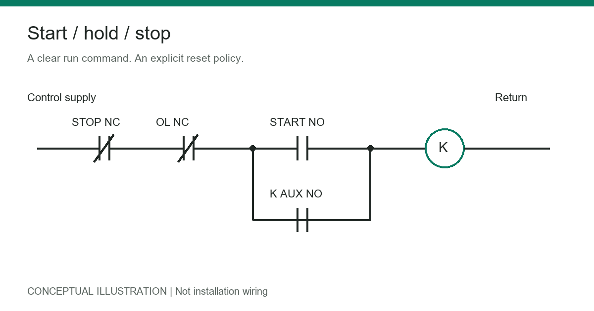
Table of Conent
Table of Conent
A start stop wiring schematic shows how a momentary START button energizes a relay or contactor and how a STOP button interrupts that command. In a conventional three-wire control circuit, an auxiliary contact keeps the coil energized after the operator releases START. Opening STOP removes coil power and releases the holding contact.
The essential design decision is where the run command is stored and how it is cleared. A relay holding circuit, PLC program, and microcontroller-based PCB can produce similar operator behavior, but they do not have identical fault responses. Define normal stopping, power-loss behavior, overload response, and safety functions before selecting components or laying out a control board.
This guide explains control logic, not a site-specific installation. Mains wiring and machinery commissioning require qualified personnel, applicable electrical requirements, and the equipment manufacturer’s instructions. An ordinary start-stop circuit is not a complete emergency-stop system.
How to Read a Basic Three-Wire Start-Stop Circuit
The basic control path contains a normally closed STOP contact, a normally open START contact, and a relay or contactor coil. A normally open auxiliary contact belonging to that relay or contactor connects in parallel with START. Where an overload relay is fitted, its normally closed trip contact commonly sits in series with the coil command.
Read the schematic in its stated normal condition: pushbuttons released, coils de-energized, and protective devices untripped. Normally open and normally closed describe contact states in that condition, not whether the motor is normally running.
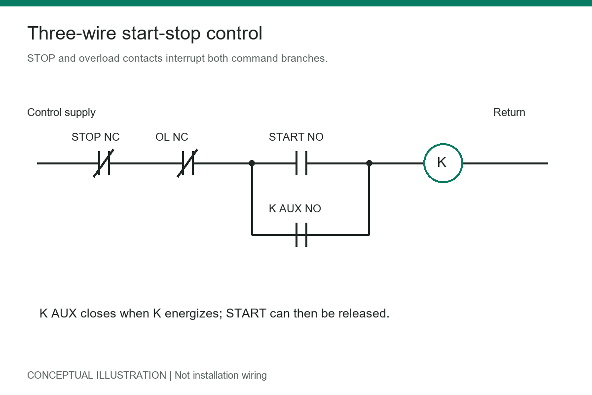
Conceptual control schematic. Component terminal numbers and installation wiring are intentionally omitted.
| Element | Normal state | Function |
|---|---|---|
| STOP pushbutton | Closed | Opens the shared coil-control path when pressed |
| START pushbutton | Open | Briefly completes the path to energize the coil |
| K auxiliary contact | Open | Closes with K to maintain the run command |
| Overload trip contact | Closed when untripped | Opens the coil-control path after a trip |
| K coil | De-energized | Operates the associated contacts when supplied correctly |
The STOP contact must interrupt both the START path and the holding path. Putting STOP only in the START branch lets the auxiliary contact bypass it. Likewise, the holding contact must belong to the device whose energized state it is meant to maintain.
For a broader explanation of symbols and terminal relationships, see the guide to reading wiring diagrams. A schematic explains electrical relationships; a terminal wiring drawing explains physical connections. A PCB netlist and connector pinout must agree with both.
What Happens When START or STOP Is Pressed?
Initially, STOP and the untripped overload contact are closed, while START and the auxiliary contact are open. No complete coil path exists.
Pressing START completes the path and energizes K. Its normally open auxiliary contact closes. Releasing START then leaves a complete path through the auxiliary contact, often called a seal-in or holding contact.
Pressing STOP opens the common series path. K de-energizes, its auxiliary contact opens, and releasing STOP does not normally restart the circuit. The operator must issue another START command.
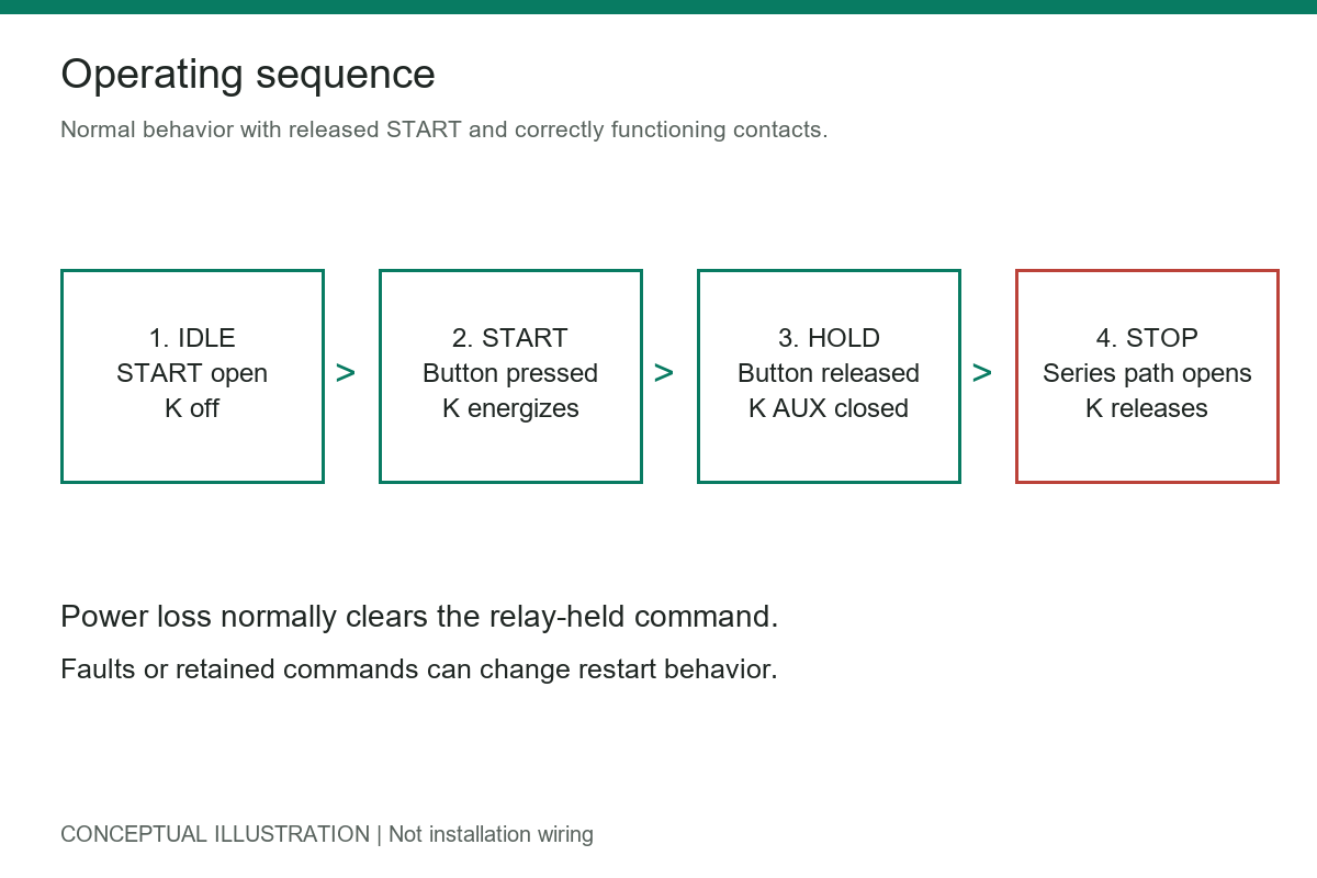
Operating sequence for a conventional momentary-button holding circuit.
Loss of control power also normally releases K and its holding contact. When power returns, the circuit remains off if START is released and all contacts function correctly. Do not interpret this as guaranteed restart prevention under every fault. A stuck START contact, welded auxiliary contact, retained software command, or different controller configuration can change the response.
Specify and test the simultaneous-button case. In the illustrated series STOP arrangement, an open STOP contact interrupts the coil path even when START is closed. In software, implement an explicit stop-dominant rule rather than relying on program scan order.
Two-Wire Versus Three-Wire Control
Two-wire control commonly uses a maintained contact, such as a selector switch or process switch, to command operation. If that contact remains closed after control power returns, the equipment may start again. This can suit some automatic processes, but it must match the intended operating and safety requirements.
Three-wire control commonly uses momentary START and STOP buttons plus a holding contact. Its normal loss-of-power response clears the relay-held run command. The terms describe control arrangements, not a universal count of every conductor in a machine.
| Design question | Maintained-command control | Momentary-button holding control |
|---|---|---|
| Where is the command held? | Maintained switch or external command | Auxiliary contact or equivalent logic |
| What follows power restoration? | May resume if the command remains active | Normally waits for a new START |
| Typical use | Process-driven automatic operation | Operator-initiated operation |
| What must be checked? | Restart authorization and external logic | Holding path, reset behavior, and contact faults |
A variable-frequency drive may offer either arrangement through configurable digital inputs. Follow its exact input configuration and wiring instructions. Do not assume a contactor-style circuit can be copied directly to a drive, or that opening an input removes hazardous energy.
Selecting Buttons, Relays, and Contactors
Match the Control Supply and Coil
Select the coil for the actual supply type and voltage range. AC and DC coils are not interchangeable simply because their nominal voltage numbers match. Check pickup and dropout specifications, duty rating, ambient conditions, and the supply’s ability to support coil energization.
For a DC relay driver, evaluate coil current at relevant supply and temperature limits, not only its nominal value. Select the transistor or MOSFET, its drive circuit, and protection network together. The basic electronic components guide provides background on the device types involved.
Check Contact Ratings for the Actual Load
A pushbutton in the control circuit switches coil or input current, not necessarily motor current. Its contact rating must suit the voltage, load type, and switching duty. DC inductive switching can demand a different rating from a resistive AC load.
A motor contactor must be selected for the motor application and required utilization duty. A small PCB relay with an apparently adequate resistive-current rating is not automatically suitable for motor starting. Check inrush, inductive load ratings, electrical life, and protection coordination with the relevant manufacturer.
Distinguish Protection Functions
Overload protection, short-circuit protection, and personnel safety perform different jobs. An overload trip contact can remove the run command, but it does not replace correctly coordinated branch protection. A STOP command does not replace an isolating device or lockout procedure.
For multiple operating stations in the conventional arrangement, normally closed STOP contacts are generally placed in series and normally open START contacts in parallel. Verify the complete drawing, conductor faults, station identification, and application requirements before commissioning.
Translating Start-Stop Logic Into a PCB
Separate the Command Circuit From the Power Circuit
Identify what the PCB actually controls: a low-voltage relay coil, a contactor interface, a drive input, or another power stage. Keep the high-current or high-voltage load path separate from sensitive inputs and logic as appropriate to the architecture.
Choose connector ratings, copper geometry, insulation spacing, and protective parts from the actual voltages, currents, environment, and applicable requirements. There is no universal trace width or clearance that makes every start-stop board suitable for industrial machinery.
Design Coil Suppression and Release Behavior Together
A DC coil stores magnetic energy. Interrupting its current without a suitable suppression path can overstress the driver. A flyback diode is one common option, but its relatively low clamp voltage can extend release time. A diode-plus-Zener or TVS arrangement can allow faster release when properly selected, at the cost of greater voltage stress.
Check the coil manufacturer’s guidance and any built-in suppression. Confirm clamp voltage, transient energy, driver voltage margin, and release timing. A simple diode across an AC coil is not an appropriate substitute for an AC-rated suppression network.
Condition Inputs and Define Reset States
Mechanical pushbuttons bounce, and long cables can couple noise into logic inputs. Use suitable input conditioning, protection, and debounce for the selected interface. Ensure GPIO voltage limits remain satisfied during transients and when one part of the system is unpowered.
In a microcontroller design, define power-on reset, brownout, watchdog recovery, communication loss, and firmware update behavior. The output should enter the specified non-running state until an authorized command is accepted. An ordinary MCU input and program are not automatically a safety-rated architecture.
The open-drain versus push-pull guide is relevant when choosing logic interfaces. Output topology alone does not establish compatibility with a 24 V field circuit; check the full electrical interface.
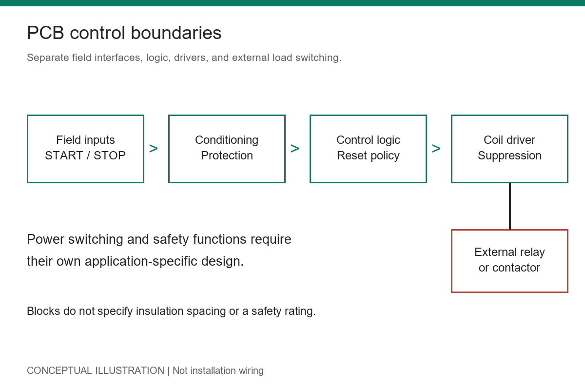
Functional architecture only. This illustration does not specify a safety-rated circuit or insulation dimensions.
A prototype PCB assembly build can support evaluation of the physical connector arrangement, driver heating, and test access before a production release. Assembly inspection cannot replace application-level validation of restart and fault behavior.
Preparing a control-board prototype? Request an engineering and quotation review with your schematic, Gerber files, BOM, placement data, build quantity, control supply, and test requirements. State the required coil-release and restart behavior so those requirements can be discussed before the build is quoted.
Common Faults and How to Investigate Them
Troubleshoot with the equipment secured and hazardous energy isolated. Never bypass STOP, overload protection, or a safety circuit to keep equipment running. Any necessary energized measurements require qualified personnel and an appropriate procedure.
| Symptom | Possible cause | Review focus |
|---|---|---|
| Runs only while START is held | Holding contact is missing, open, or wired incorrectly | Auxiliary contact identity and parallel branch |
| STOP fails to remove the command | Holding path bypasses STOP or the input logic is wrong | Shared series interruption and stop-dominant logic |
| Coil chatters | Inadequate supply, loose connection, or unsuitable coil | Supply under pickup load and coil specifications |
| Restarts after power returns | Maintained command, stuck contact, or retained logic | Power-restoration policy and actual command state |
| Controller resets when the coil switches | Supply disturbance or poor transient control | Suppression, supply paths, grounding, and input protection |
These are diagnostic possibilities, not proof of a particular fault. A de-energized coil also does not prove that the load is disconnected: power contacts may weld, and another energy source may exist. Determine whether feedback or monitored switching is required by the application.
Why an Ordinary STOP Is Not an Emergency Stop
A normally closed STOP contact provides a useful normal-control behavior: opening its circuit removes the command. That alone does not establish a safety function. Some faults can defeat the stop action, and a single ordinary relay does not automatically detect them.
Emergency stopping requires an application-specific risk assessment and a suitable architecture. Depending on the machine, that may involve monitored contacts, safety relays, safety controllers, drive safety functions, and defined reset behavior. The required stopping method also depends on whether immediate power removal creates another hazard.
Keep normal operational commands distinct from safety requirements in the schematic and test specification. Follow the applicable machinery standards and component instructions. For a manufacturer reference on conventional control arrangements, see Rockwell Automation’s Typical Wiring Diagrams.
What to Include in a Control-Board Build Package
Provide the schematic revision, fabrication files, BOM with manufacturer part numbers, placement data, connector pinout, and assembly notes. Identify coil polarity, suppression parts, optional components, and any configuration settings that affect restart behavior. The PCB assembly document checklist is a useful starting point.
Define functional tests separately from visual inspection: START and release, STOP, simultaneous commands, overload input, loss and restoration of power, and applicable reset or fault conditions. State supply ranges, expected outputs, timing limits, and acceptance criteria rather than asking only for a board that “works.”
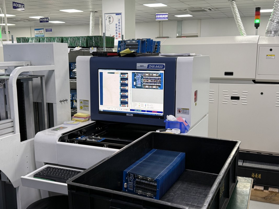
Local factory image showing inspection equipment. It is not a test record for a start-stop control board; circuit behavior requires its own functional test plan.
Conclusion
A useful start stop wiring schematic makes the holding path, common STOP interruption, and restart behavior explicit. Select components for their actual load and control duty, then validate the PCB interface, suppression, and reset states. Treat emergency stopping as a separate safety-design task.
Ready to plan a build? Request a quote with the controlled schematic revision, Gerbers, BOM, placement files, quantity, and functional test specification. Include the intended load interface and any safety-related boundaries so the project requirements and quotation scope can be confirmed.
Latest Blog



Contact Info
Phone: +86-755-82882936
Email: [email protected]
WhatsApp: +86-13570802455
Wechat: +86-13570802455
Address: 2nd floor,D Bldg.,Electric Link Technology Bldg.,Gongming,Guangming New Dist.,518106 Shenzhen, China