
What Are Computer Jumpers? Functions, Settings, and PCB Design
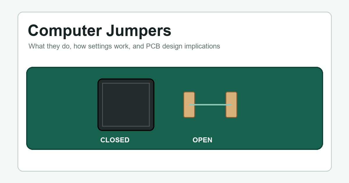
Table of Conent
Table of Conent
A computer jumper is a small conductive shunt used to connect selected pins on a circuit board. Installing, removing, or repositioning the shunt changes an electrical condition that hardware reads as a configuration choice. Before software-configurable firmware became common, jumpers were widely used for settings such as drive roles, clock options, voltage selection, and clearing stored configuration data.
Modern products use fewer jumpers, but the design principle remains useful. A jumper gives engineers a visible, low-cost, nonvolatile hardware option that does not depend on a user interface. The same simplicity can also create service mistakes if the pinout, default state, or power-off procedure is unclear.
What Is a Computer Jumper?
In computer hardware, the word jumper usually refers to a removable plastic cap with an internal metal contact. The cap fits over two adjacent header pins and electrically joins them. The complete feature therefore includes the header, the conductive shunt, the PCB nets connected to the pins, and the circuit that interprets the resulting state.
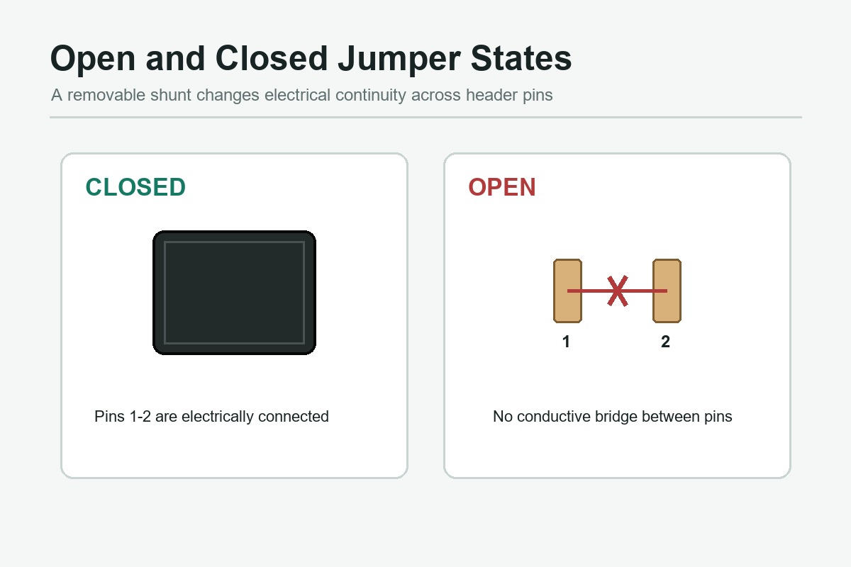
A two-pin jumper has two basic conditions:
- Closed: the shunt covers both pins, creating electrical continuity.
- Open: the shunt is removed or parked on one pin, so the two signal points are not connected.
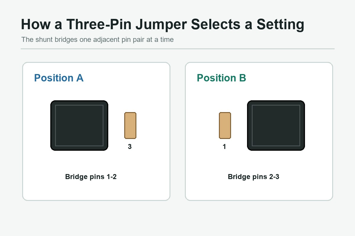
A three-pin arrangement supports two selectable positions. Bridging pins 1-2 can represent one mode, while bridging pins 2-3 represents another. The electrical meaning is determined by the schematic, not by a universal convention. Always use the board documentation or silkscreen instead of assuming that one physical position means “enabled.”
How Does a Jumper Setting Work?
The jumper normally connects a logic input to ground, a supply rail, or another defined signal. A pull-up or pull-down resistor holds that input at a known level when the shunt is absent. At startup, a controller, chipset, or other circuit reads the level and selects the corresponding behavior.
For example, an input may read logic high when the pins are open and logic low when the shunt connects the input to ground. That is only an example. The opposite arrangement is equally possible, and some jumpers route analog signals or power rather than logic inputs. Designers must check voltage, current, contact resistance, and fault behavior before using a removable shunt in a non-logic path.
The distinction between an electrical schematic and a wiring view matters here. A schematic shows the function of the nets and components, while the assembly drawing shows where the physical header and pin 1 are located. Engineers who need to connect those views can use this guide to read wiring diagrams and translate circuit intent into PCB-ready documentation.
Common Uses of Jumpers in Computer Hardware
Clearing CMOS or Stored Firmware Settings
Many desktop motherboards include a header for clearing stored firmware configuration. Depending on the design, the required procedure may involve moving a shunt between pins, briefly bridging two pins, or using a dedicated button. Power and battery instructions vary by product. Moving the jumper while the board is energized can create an unintended short or leave data in an undefined state, so the motherboard manual controls the procedure.
Legacy Hard Drive and Optical Drive Configuration
Parallel ATA drives commonly used jumpers to select master, slave, or cable-select behavior. Some storage devices also used jumper positions to limit transfer modes or change compatibility settings. These examples explain why “jumpers on a motherboard” and “hard drive jumper settings” remain common search questions even though newer SATA and NVMe systems usually configure devices electronically.
Service, Test, and Manufacturing Modes
A jumper can expose a controlled hardware option for production testing, calibration, boot-mode selection, or field service. It may be more dependable than a software menu when firmware is not yet programmed or the unit cannot boot. However, any service jumper that can disable protection or enter a test state needs restricted access and explicit documentation.
Product Variants on a Shared PCB
One PCB design can support several product variants by changing a jumper position or fitted component option. This can reduce layout duplication, but it transfers configuration control to the BOM, assembly instructions, inspection plan, and traceability records. The design is only economical when the correct variant can be assembled and verified consistently.
For a prototype that uses configuration headers or variant options, send the Gerber files, BOM, pick-and-place data, assembly drawings, required quantities, and the default jumper position for a prototype PCB assembly review.
Jumper Cap vs Jumper Wire vs Zero-Ohm Resistor
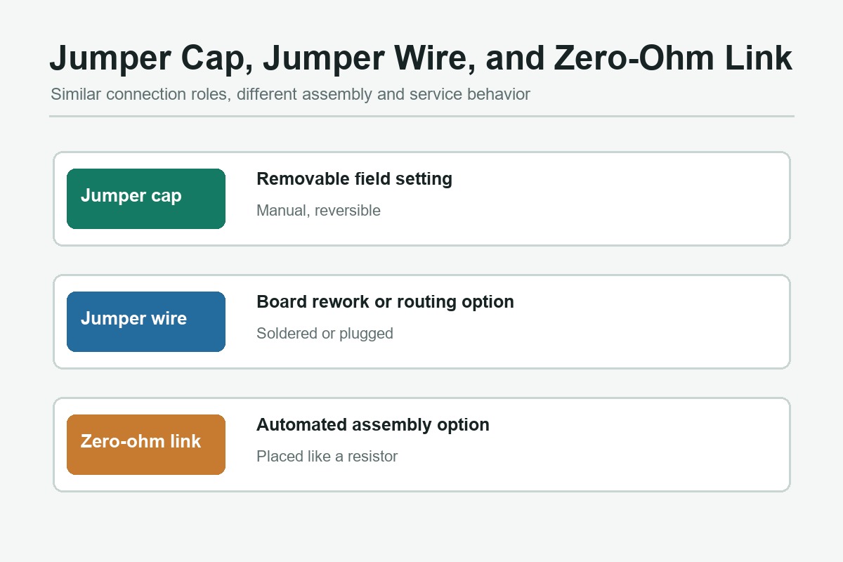
These parts can all create an electrical connection, but they solve different manufacturing and service problems.
| Option | Best suited to | Main advantage | Main limitation |
|---|---|---|---|
| Jumper cap and header | Field-selectable or service settings | Visible and reversible without soldering | Manual placement and possible loss or misconfiguration |
| Jumper wire | Rework, repair, or routing around a PCB constraint | Flexible connection between separated points | Labor, routing control, and workmanship requirements |
| Zero-ohm resistor | Automated assembly options and routing bridges | Compatible with standard SMT placement | Not intended for casual field changes |
| Solder bridge | Low-cost configuration changed infrequently | No separate component may be needed | Requires soldering and can be ambiguous after rework |
| DIP switch | Repeated user or service configuration | Clear, tool-free switching | More board area and component cost |
For a production design, the decision should consider who changes the setting, how often it changes, whether an enclosure blocks access, and how the assembly line verifies the final state. A removable cap is not automatically the least expensive option once manual placement, inspection, packaging, and field-support costs are included.
PCB Design Rules for Reliable Jumper Settings
Define a Stable Electrical State
Do not leave a configuration input floating when the shunt is absent. Use an appropriate pull-up or pull-down resistor and confirm that leakage, noise, startup timing, and input thresholds cannot create an indeterminate state. If the jumper switches power or an analog path, review current rating, transient conditions, creepage, and clearance instead of treating it as a simple digital input.
Make the Default Position Obvious
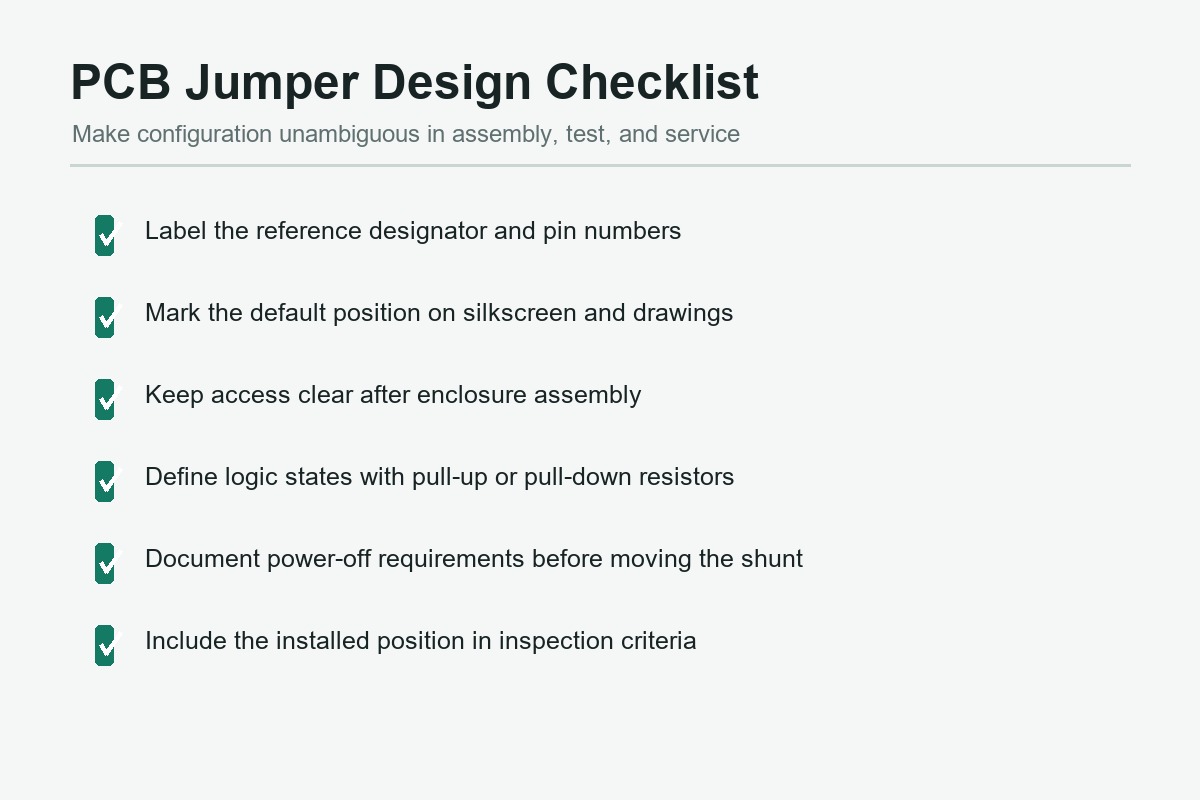
Label the reference designator, pin 1, and valid positions on the silkscreen when space permits. The assembly drawing should state the shipped position in words as well as by graphic notation. Avoid labels that become hidden under the shunt. A technician should be able to identify the correct position without reversing the enclosure orientation mentally.
Design for Access and Retention
Check access after cables, shields, daughterboards, heat sinks, and the enclosure are installed. Provide finger or tool clearance without placing the header where a dropped cap can contact energized conductors. In products exposed to vibration, contamination, or frequent handling, evaluate shunt retention and consider a locked connector, switch, or software-controlled alternative.
Control the Configuration in Manufacturing Data
The BOM should identify the header and shunt separately and state whether the cap is fitted, omitted, or parked. Assembly notes should map every sellable variant to a position. Inspection criteria should verify the installed state, not merely the presence of the header. The required manufacturing package is broader than Gerbers alone; this overview of documents required for PCB assembly explains how BOM, centroid, drawings, and test requirements work together.
During component and footprint review, confirm pitch, pin length, current rating, contact plating, mating cycles, and supplier part numbers. The surrounding circuitry should also be reviewed alongside the basic electronic components that establish default logic levels and protect the input.
Assembly and Test Risks
Jumpers introduce a configuration state that visual inspection or functional test must capture. Common failures include a cap shifted by one pin, the wrong default position, an omitted shunt, bent header pins, a cap supplied loose instead of installed, and documentation that disagrees with the schematic.
Automated optical inspection may verify header placement, but the final shunt position can require a dedicated inspection rule or manual check because the dark cap may obscure pin geometry. Functional testing provides stronger evidence when each state produces a measurable result. If only one shipped configuration is valid, the test fixture or firmware should identify the wrong state rather than allowing an incorrectly configured unit to pass.
A full-service PCB assembly workflow should treat the jumper position as controlled build data. The quotation package needs enough information to price manual insertion, inspection, functional testing, variant separation, and any loose accessories accurately.
How to Read or Change a Jumper Safely
- Identify the exact board model and revision.
- Find the jumper reference designator and pin numbering in the product manual or assembly drawing.
- Record the original position before removing the cap.
- Power down the product and follow the documented discharge or battery procedure.
- Move the shunt only to a documented valid position. Do not guess from a similar board.
- Check that the cap is fully seated and not offset by one pin.
- Restore power, verify the expected behavior, and update service records when applicable.
Lenovo’s overview of computer jumpers provides additional general background. Product-specific manuals still take precedence because jumper functions and safe procedures are not universal.
When Should a New PCB Use a Jumper?
Use a removable jumper when a small number of hardware modes must remain available without firmware, the setting changes infrequently, and a trained assembler or technician can access it safely. Prefer a zero-ohm resistor when the option is selected during automated assembly and is not intended for field adjustment. Prefer a switch when repeated access is expected, and consider firmware configuration when the product needs a guided user experience, access control, or remote management.
The best choice is the one that makes the intended state electrically stable, physically obvious, manufacturable, testable, and difficult to misuse. If a jumper is retained, define its default position in the schematic, BOM, assembly drawing, inspection plan, and test specification.
Preparing a PCB assembly quotation? Send the Gerber files, BOM, pick-and-place data, assembly drawings, quantity, test requirements, and a configuration matrix showing each jumper position. OrinewPCB can then review the package through the PCB assembly service page and identify any documentation gaps before production.
Latest Blog



Contact Info
Phone: +86-755-82882936
Email: [email protected]
WhatsApp: +86-13570802455
Wechat: +86-13570802455
Address: 2nd floor,D Bldg.,Electric Link Technology Bldg.,Gongming,Guangming New Dist.,518106 Shenzhen, China