
Diode vs Triode: Characteristics, Uses, and PCB Design Differences
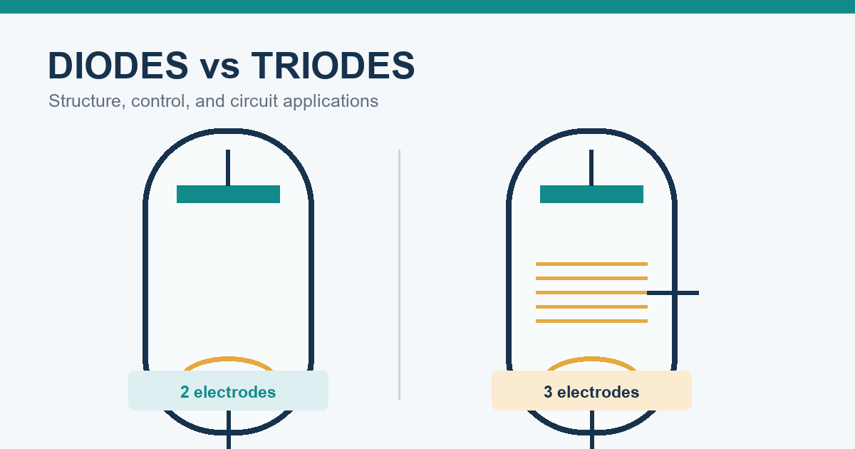
Table of Conent
Table of Conent
A diode and a triode both control electron flow, but they do fundamentally different jobs. A diode has two active electrodes and primarily permits current in one direction. A triode has three active electrodes; its additional control grid allows a relatively small input voltage to regulate a larger current, making amplification and controlled switching possible.
The terminology needs one important clarification. In the historical comparison “diode and triode,” both words normally refer to vacuum tubes: a two-electrode vacuum diode and a three-electrode vacuum triode. In modern electronics, however, “diode” usually means a semiconductor PN-junction device, while triodes survive mainly in audio, radio-frequency, high-voltage, restoration, and specialist equipment. A triode is also not simply another name for a three-terminal transistor.
What Is a Diode?
A diode is a two-terminal or two-electrode device designed for asymmetric conduction. In a modern semiconductor diode, the terminals are the anode and cathode. Forward bias lowers the junction barrier and permits substantial current; reverse bias normally allows only leakage until the device reaches its rated breakdown region.
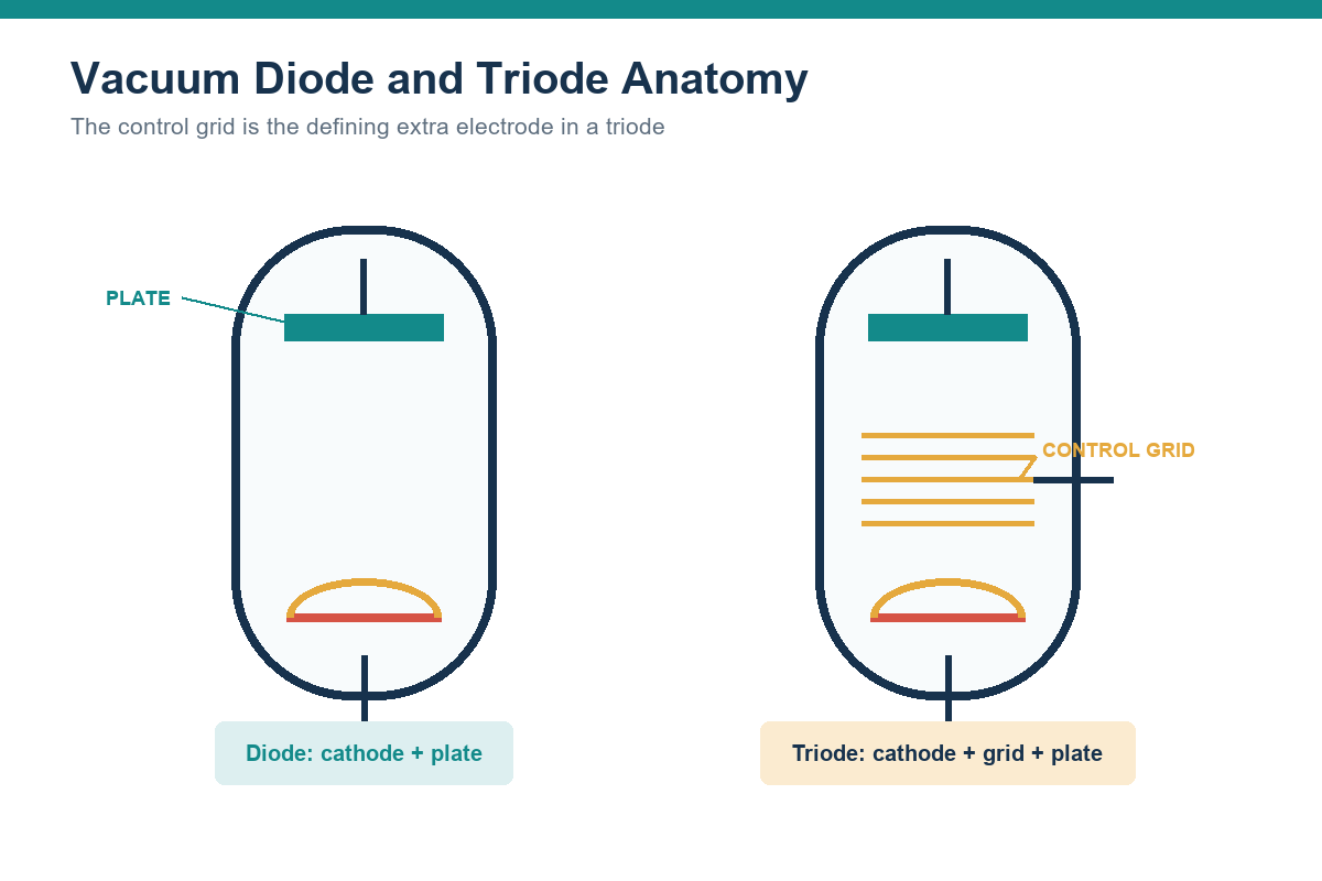
A vacuum diode uses the same functional idea but a different physical mechanism. Its heated cathode emits electrons through thermionic emission. When the plate, historically called the anode, is positive relative to the cathode, it attracts those electrons and current flows through the external circuit. Reversing the polarity does not cause comparable conduction because the unheated plate is not an effective electron source.
This directional behavior makes diodes useful for rectification, reverse-polarity protection, signal detection, clamping, voltage reference functions, light emission, and many other tasks. The correct device depends on reverse-voltage rating, forward current, switching speed, forward drop, leakage, capacitance, temperature, surge conditions, and package constraints.
What Is a Triode?
A triode is a vacuum tube with three active electrodes: cathode, control grid, and plate. A heater raises the cathode to an operating temperature. Electrons emitted by the cathode travel toward the positively biased plate. The control grid sits between them and changes how many electrons reach the plate.
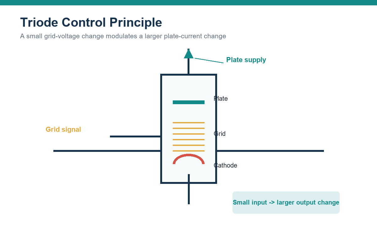
A grid that becomes more negative relative to the cathode repels more electrons and reduces plate current. Making the grid less negative allows more current. Because a small change in grid voltage can produce a larger change in plate current and in the voltage across the plate load, the triode can amplify a signal.
The heater is essential, but it is not counted among the three active electrodes named by “triode.” Some tubes use a directly heated cathode in which the filament itself emits electrons. Others use an indirectly heated cathode electrically separate from the heater. That distinction affects heater supply, isolation, hum, warm-up behavior, and circuit implementation.
Diode and Triode: Side-by-Side Comparison
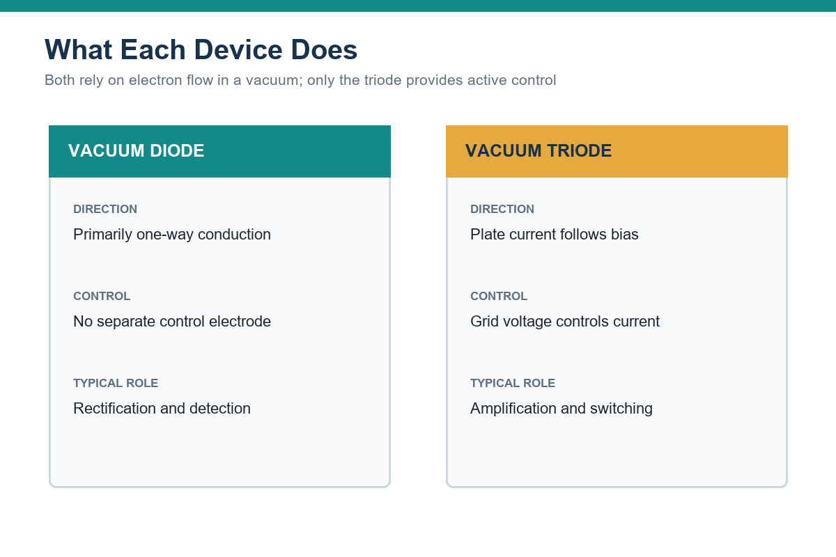
| Characteristic | Vacuum Diode | Vacuum Triode |
|---|---|---|
| Active electrodes | Cathode and plate | Cathode, control grid, and plate |
| Primary function | One-way conduction | Control and amplification |
| Input control | No separate control electrode | Grid voltage controls plate current |
| Typical circuit role | Rectifier or detector | Voltage amplifier, driver, oscillator, or controlled switch |
| Power needs | Heater plus plate supply | Heater, plate supply, and defined grid bias |
| Signal behavior | Nonlinear conduction based mainly on polarity | Transfer characteristic depends on grid voltage and plate voltage |
| Common modern use | Specialist tube equipment; semiconductor diodes dominate general PCB designs | Audio, RF, high-voltage, legacy, and specialist equipment |
| Key design concern | Peak inverse voltage, current, heat, and heater requirements | Bias point, gain, plate dissipation, heater routing, stability, and noise |
The table compares vacuum devices so the terminology remains consistent. A semiconductor diode shares the two-terminal rectifying function but differs greatly in size, voltage drop, efficiency, thermal behavior, switching speed, and mounting method.
How a Triode Controls and Amplifies a Signal
The control grid gives the triode its defining capability. In a common-cathode voltage amplifier, a DC plate supply feeds the tube through a plate resistor or another load. The circuit establishes a grid-to-cathode bias that places the tube at a chosen operating point. A small AC signal changes the grid voltage around that point, which changes plate current. The changing plate current creates a larger voltage variation across the plate load.
Useful design quantities include amplification factor, transconductance, plate resistance, maximum plate voltage, maximum plate dissipation, heater voltage and current, interelectrode capacitance, and the recommended operating curves. These values are related, so a designer should use the manufacturer’s data sheet and characteristic curves rather than selecting a tube from a single headline rating.
Bias also determines linearity and headroom. An operating point too close to cutoff can clip one side of the waveform; one too close to excessive plate current can violate dissipation limits or shorten tube life. Cathode bias, fixed bias, and grid-leak bias each impose different component and safety requirements.
Preparing a tube-based prototype? Provide the schematic, BOM, tube and socket part numbers, board outline, operating voltages, mechanical constraints, and test expectations for a prototype PCB assembly review.
Common Uses of Diodes and Triodes
Diode Applications
Rectification is the most direct use. A diode can convert one polarity of an AC waveform into pulsating DC, while multiple diodes can use both halves of the waveform. The choice between half-wave and full-wave rectifier circuits affects ripple frequency, transformer utilization, diode stress, filtering, and available output power.
Other diode applications include reverse-polarity protection, flyback paths for inductive loads, transient suppression, signal steering, envelope detection, voltage multiplication, reference generation, photodetection, and light emission. These functions may use rectifier, Schottky, Zener, TVS, PIN, photodiode, or LED structures rather than one interchangeable “general diode.”
Triode Applications
Triodes are valued when their transfer characteristics, overload behavior, voltage handling, or historical authenticity are part of the product requirement. Common examples include preamplifier stages in musical-instrument and high-fidelity audio equipment, oscillators and drivers in radio circuits, laboratory instruments, restoration of legacy systems, and specialized high-voltage or RF equipment.
A power triode can control substantial current, but it also requires careful bias, cooling, insulation, and mechanical design. In many general-purpose products, transistors or integrated circuits provide equivalent functions with lower supply voltage, reduced heat, smaller size, and easier automated assembly. Selecting a triode therefore needs a circuit-level reason, not just a preference for the component category.
Is a Triode the Same as a Transistor?
No. A vacuum triode and a transistor can both amplify or switch, and the words “triode” and “three-terminal device” sometimes lead to confusion. Their construction and operating physics are different.
A vacuum triode controls electron flow through a vacuum with an electrostatic grid and normally needs a heater. A bipolar junction transistor controls collector current through base-emitter behavior in semiconductor material. A field-effect transistor controls channel current with an electric field at its gate. Their bias methods, input impedance, drive requirements, operating voltages, failure modes, and thermal limits cannot be treated as interchangeable.
Schematic symbols are also distinct. Tube diagrams identify plate, grid, cathode, and heater connections, while BJT and FET drawings use different terminal conventions. This guide to transistor schematic symbols helps distinguish NPN, PNP, MOSFET, and JFET devices from vacuum-tube symbols.
PCB Design Considerations for Diode and Triode Circuits
Tube circuitry can be mounted on a PCB, but the board must accommodate electrical, thermal, and mechanical conditions that are uncommon in low-voltage digital products.
Voltage, Creepage, and Clearance
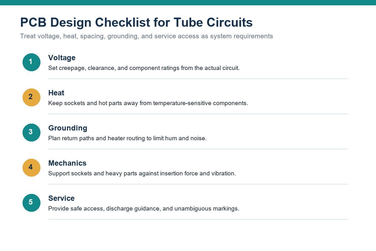
Plate supplies may be high enough to cause dangerous shock and PCB surface arcing. Determine conductor spacing from the actual working voltage, pollution degree, material group, altitude, applicable product standard, and transient environment. Do not copy a clearance value from an unrelated low-voltage layout. Include discharge paths for stored energy and define a safe service procedure for capacitors that can retain charge after power is removed.
Heat and Component Placement
Tube envelopes and sockets can become hot. Keep electrolytic capacitors, connectors, plastics, and other temperature-sensitive basic electronic components outside the expected hot zone. Evaluate copper temperature, board material, ventilation, enclosure airflow, and spacing under worst-case ambient and operating conditions. The socket footprint must match the exact part, including pin diameter, retention features, orientation key, and keepout.
Heater Routing and Grounding
Heater current can introduce hum and magnetic coupling into high-impedance signal nodes. Route heater conductors as a controlled pair, keep them away from sensitive inputs, and choose AC or DC heater operation based on noise requirements. Establish deliberate signal, power, and chassis return paths. A careless ground layout can defeat an otherwise correct schematic.
Mechanical Support and Assembly
Tube insertion and removal place force on the socket and PCB. Heavy or frequently serviced tubes may need chassis-mounted sockets, brackets, or board stiffening. Verify that solder joints are not the only structural restraint and that the enclosure allows safe replacement without stressing adjacent parts.
Sockets, large capacitors, transformers, and many legacy parts use through-hole leads. A through-hole PCB assembly plan should define insertion, lead trimming, soldering, cleaning, inspection, mechanical support, and any components installed after wash or conformal coating.
How to Choose Between Them
The choice is usually functional rather than competitive: use a diode when the circuit needs rectification, clamping, protection, detection, light emission, or another two-terminal nonlinear function. Use a triode when the design specifically requires vacuum-tube amplification, oscillation, or controlled current behavior.
Before choosing a device, answer these questions:
- Is the requirement one-way conduction or active signal control?
- Does the product genuinely require tube behavior, voltage handling, sound character, RF performance, or historical compatibility?
- What supply rails, heater power, warm-up time, and standby power are acceptable?
- What voltage, current, frequency, noise, distortion, and thermal limits apply?
- Can the enclosure provide ventilation, guarding, service access, and shock protection?
- Are the tube, socket, transformer, and replacement parts available for the expected product life?
- How will assembly inspection and functional testing verify bias, gain, ripple, noise, and safe discharge?
For most compact, battery-powered, or high-volume PCB products, semiconductor diodes and transistors are the practical choice. For specialist equipment where vacuum-tube behavior is intentional, the triode remains a valid component, but the surrounding power supply, mechanics, safety, and service strategy become part of the design decision.
Key Takeaway
A diode provides two-electrode, primarily one-way conduction; a triode adds a control grid so a small input can regulate and amplify a larger current. In the classic comparison, both devices are vacuum tubes. Modern semiconductor diodes and transistors perform related circuit functions through different physical structures and should not be described as identical replacements.
For manufacturing, the device choice affects much more than the schematic. Voltage spacing, heater routing, thermal management, socket mechanics, grounding, component availability, inspection, and functional testing all need to appear in the production package. For a PCB assembly quotation, provide Gerber files, BOM, pick-and-place data where applicable, assembly drawings, quantities, voltage and safety notes, and test requirements for a PCB assembly review.
Latest Blog





Contact Info
Phone: +86-755-82882936
Email: [email protected]
WhatsApp: +86-13570802455
Wechat: +86-13570802455
Address: 2nd floor,D Bldg.,Electric Link Technology Bldg.,Gongming,Guangming New Dist.,518106 Shenzhen, China