
PCB Microsection Analysis: Sample Selection, Measurements, and Report Review
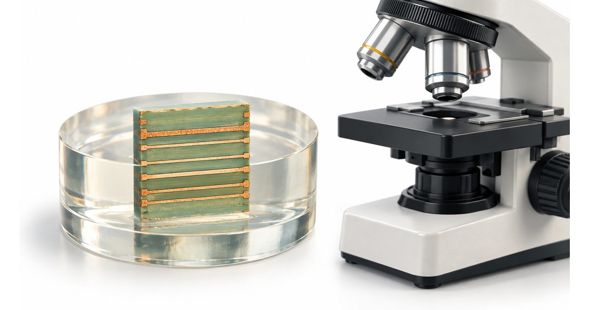
Table of Conent
Table of Conent
PCB microsection analysis exposes a selected internal plane so an engineer can inspect board construction and plated structures. It can support incoming acceptance, process qualification, or a failure investigation, but a convincing image is not enough. The section must represent the feature in question, preserve traceability, and be evaluated against the correct requirement.
For buyers, the most useful deliverable is a report connecting the sample location, preparation condition, measurements, and conclusion. This guide explains how to request that evidence, recognize the limits of a two-dimensional section, and avoid confusing a preparation artifact with a manufacturing defect. It is not a laboratory recipe or a replacement for the applicable performance specification.
Start with the decision the section must support
Define the question before authorizing destructive sampling. A routine lot inspection may evaluate specified construction features on designated coupons. A qualification program may require sections after defined conditioning. A failure investigation may need a particular board and location preserved before any further processing.
The official IPC-TM-650 Method 2.1.1F provides preparation guidance for evaluating laminates and plated structures. It directs evaluation to the applicable printed-board performance specification. A preparation method therefore does not, by itself, establish a universal pass limit.
Write a short inspection objective: identify the construction feature, the condition to be examined, and the acceptance or investigative question. “Check PCB quality” is too broad to establish a useful sectioning plan. If the objective is unclear, the laboratory may produce technically good images that cannot answer the purchasing question.
Agree who may authorize removal of material, which boards are available for sampling, and how remaining specimens will be retained. A destructive section should not consume the only evidence of an intermittent issue without a documented investigation plan.
Select a traceable specimen and section plane
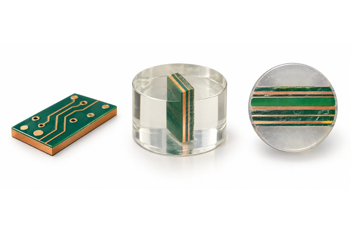
Identify whether the specimen comes from an actual circuit or a conformance coupon, and record its relationship to the production panel and lot. A coupon may support a defined inspection requirement, but it should not silently replace a suspect product feature during a targeted investigation.
Use the controlled board drawing or an annotated location image to identify the feature. Record orientation and the intended plane. For complex via structures, provide the relevant stackup and design geometry so the laboratory understands what needs to be intersected.
A section reveals what exists in its selected plane; it is not a complete three-dimensional examination. Plan additional sections when a single view cannot answer the question. Do not claim that a feature absent from one image is absent everywhere in the board.
Our via-in-pad design guide provides context for filled and capped structures that may require focused construction review. State whether the investigation concerns the hole wall, fill, cap, or connection to a land instead of treating these as one interchangeable attribute.
Mark sample identity before cutting and keep that identity on the mount, images, and report. Traceability should survive transfers between the supplier, customer, and laboratory. A photograph labeled only “sample one” may become unusable when multiple lots enter the same investigation.
Review preparation quality before judging the board
Sample removal, mounting, grinding, polishing, and any etching are part of the evidence chain. Preparation can affect the appearance of a structure. Ask the laboratory to assess image quality and document any condition that prevents a reliable observation.
The IPC-9241 preparation-guideline preview treats microsection preparation as a process and identifies topics including scratched surfaces, smeared metal, and rounded interfaces. These are useful review concerns, not instructions to dismiss every suspicious feature as an artifact.
When a feature is ambiguous, ask for the laboratory’s reasoning and any agreed additional examination. Preserve the original image and identify subsequent preparation or viewing changes. Do not replace an unfavorable image with a cleaner one without explaining whether the same feature and specimen remain under review.
Keep as-polished and etched observations distinguishable where they are part of the evaluation. Method 2.1.1F discusses documenting possible separations before microetching and checking afterward. A report should identify the observation condition rather than presenting all images as if they were acquired at the same stage.
Send your PCB files, stackup, and proposed microsection inspection scope for a manufacturing quote review. Include the feature locations and expected report so sampling and evidence requirements can be discussed before fabrication.
Measure the requested attribute, not an attractive image
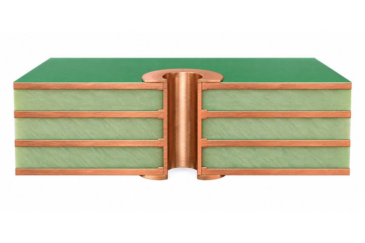
Define each requested measurement explicitly. Hole-wall plating thickness, conductor thickness, dielectric spacing, and layer registration are different attributes. A dimension recorded for one feature should not be used as evidence for another simply because both are visible in the same section.
IPC-TM-650 Method 2.2.5A addresses dimensional inspection of microsections and lists several measurable construction attributes. It requires calibrated measurement equipment and has a stated lower measurement-range limitation. Confirm that the proposed technique is applicable rather than assuming an optical image can resolve every thin coating.
Request the measurement locations, units, individual results, and the requirement used for comparison. If a report gives a minimum or average value, ask how that value was derived and which sampled locations it includes. An average must not conceal an individual result that controls acceptance.
Magnification alone is not a measurement record. Ask for calibration information and a usable scale tied to the image. Retain the original image where possible, because resizing a screenshot can separate displayed dimensions from the original measurement context.
State the controlling drawing revision and acceptance document with each conclusion. Avoid applying a limit remembered from a different board type, product class, or standard edition. The report should make its comparison reproducible for another qualified reviewer.
Keep the specimen’s exposure history visible
Identify whether the sample represents an as-fabricated board, a board after an agreed stress exposure, or a returned assembly. These are different evidence states. A post-exposure result cannot automatically stand in for the incoming construction record.
Record conditioning or assembly history when it is known, and label gaps honestly. Include any prior rework or treatment relevant to the investigation. Do not invent a history from the appearance of the sample or assume that all pieces from a lot experienced identical handling.
For comparative work, agree the specimen selection and evaluation plan before examining results. Keep treated and untreated groups separately identified. If the customer and supplier use different conditioning, resolve that difference before interpreting their results as contradictory.
A microsection is one investigation tool, not a prediction of every future reliability outcome. Decide whether the project also requires electrical, thermal, or other evaluation through the applicable qualification plan rather than implying that a clear section proves lifetime performance.
Build a report that supports disposition

A decision-ready report identifies the board revision, lot, sample source, feature location, section orientation, preparation method, specimen condition, images, measured attributes, and acceptance basis. It should separate observations from interpretations and identify unresolved limitations.
Request an overview image linking the detailed view to its location. Detailed images should retain sample identity and explain which feature is being shown. Avoid a collection of isolated close-ups that cannot be traced back to the board or coupon.
If the finding is nonconforming, record the affected samples and agreed disposition authority. If the finding is inconclusive, say so and identify the next examination needed. “No defect found in this section” is narrower than “the entire lot has no defect,” and the wording should reflect that difference.
The PCB fabrication troubleshooting guide can help organize supplier evidence and corrective-action review. Use the section report alongside the controlled construction and process records, not as a substitute for them.
Request an engineering and quotation review with your controlled drawing and required microsection report fields. Identify any special conditioning, retained samples, or independent laboratory requirements so the scope can be confirmed.
A hypothetical coupon and product disagreement
Consider a buyer whose conformance coupon report meets the agreed routine requirement, while a section from a returned board shows an unresolved feature. This is a hypothetical example, not an AssyPCB customer case.
The teams first confirm the lot relationship, feature geometry, section plane, and exposure history. They then agree whether additional product sections or other investigation are needed. Neither report should be dismissed simply because the other exists: the two specimens may represent different locations or conditions. The final disposition should state what evidence was considered and what remains uncertain.
Define inspection scope before ordering
Provide the controlled files, stackup, evaluated features, sampling plan, exposure conditions, report requirements, and acceptance documents with the RFQ. Identify permitted alternatives and require approval for deviations. Ask how sample consumption, additional laboratory work, and report delivery affect the proposed scope and schedule.
Use the published PCB manufacturing capabilities as a starting point, then confirm project-specific inspection arrangements. A general capability page is not confirmation of a custom qualification program or every laboratory method.
Submit your PCB files and inspection requirements for a project-specific quote. A traceable specimen and a clearly defined report give engineering and purchasing teams a stronger basis for acceptance than an unexplained microsection photograph.
Latest Blog
Contact Info
Phone: +86-755-82882936
Email: [email protected]
WhatsApp: +86-13570802455
Wechat: +86-13570802455
Address: 2nd floor,D Bldg.,Electric Link Technology Bldg.,Gongming,Guangming New Dist.,518106 Shenzhen, China