
Aircraft Cabin Lighting Boards: Prototype Quickly with Low-Volume Builds
Table of Conent
Table of Conent
An aircraft cabin lighting board prototype should reduce technical uncertainty without creating a one-off configuration that cannot become a controlled product. The fastest useful low-volume build starts with a complete release package, production-intent components and stackup, an explicit LED and power architecture, planned programming and test access, and a verification matrix that distinguishes engineering evaluation from equipment qualification.
Speed comes from closing decisions before material is ordered: input-power conditions, channel count, LED strings, dimming method, color and brightness targets, thermal limits, mechanical envelope, connectors, communication interfaces, EMI risks, environmental categories, assembly quantities, and required evidence. A contract manufacturer can then source, fabricate, assemble, inspect, program, and test one consistent revision instead of pausing for avoidable clarifications.
Define what the prototype must prove
Separate questions into electrical, optical, thermal, mechanical, software, manufacturing, and compliance groups. A bench prototype might prove dimming logic and current regulation. A form-fit unit might prove connector access and installation. A production-intent pilot might evaluate assembly yield, thermal behavior, EMI, environmental stress, and test coverage. One build rarely answers every question.
Write success criteria before choosing quantity. Include input-voltage range, current per channel, brightness or photometric target, dimming range, flicker limits, color behavior, communication, fault detection, startup and shutdown, thermal limits, efficiency, acoustic noise where relevant, and recovery from open or short LED conditions. Use the applicable program requirements rather than generic cabin-lighting assumptions.
| Prototype stage | Main purpose | Typical evidence |
|---|---|---|
| Engineering sample | Prove circuit and firmware concepts | Bench waveforms, current, dimming, and fault behavior |
| Form-fit sample | Confirm enclosure, connector, optics, and installation | Mechanical inspection and installed-light evaluation |
| Production-intent pilot | Validate sourcing, assembly, programming, and test | Build records, inspection, yield, and functional results |
| Qualification configuration | Support the approved equipment test plan | Exact controlled hardware, software, harness, and reports |
Freeze the power and LED architecture early
Document the aircraft power input, protection, filtering, conversion stages, LED-driver topology, string configuration, current-sense method, dimming architecture, communications, and fault outputs. Identify galvanic isolation and chassis or shield connections. Confirm which requirements belong to the board and which belong to the complete light assembly.
Switching LED drivers can create concentrated high-current and high-dV/dt loops. Texas Instruments’ LED-driver layout guidance and Analog Devices’ power-supply EMI guidance both emphasize compact switching loops, deliberate grounding, close input capacitors, and careful switch-node copper. Apply the exact device data sheet; a reference design for another product is evidence of a technique, not qualification of your board.
Choose LED bins, forward-voltage assumptions, current margin, connector contacts, wire size, protection parts, inductors, capacitors, and switches together. A late LED or harness change can alter headroom, efficiency, heat, fault thresholds, and EMI.
Use production-intent parts when they affect the result
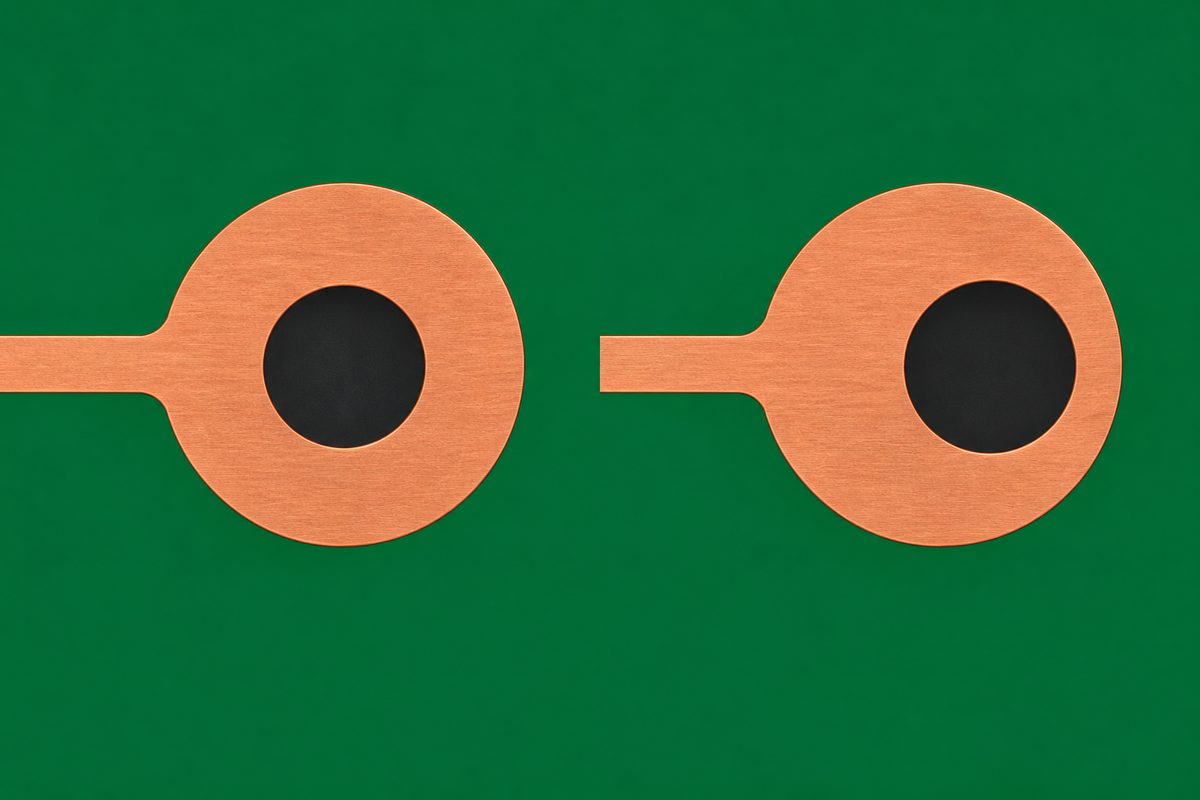
An evaluation board can help firmware development, but its layout, component grades, thermal copper, filters, connectors, and protection may differ from the intended product. For conclusions about heat, EMI, optical output, vibration, or assembly, use the planned devices and representative PCB construction wherever practical.
Control exact manufacturer part numbers and alternates. LED color and flux bins, current-sense resistors, magnetics, ceramic-capacitor bias behavior, protection-device capacitance, connector plating, and thermal-interface materials can affect results. Record approved substitutions and keep shortages from silently changing the prototype’s meaning.
Procure extra quantities for setup, attrition, destructive analysis, programming trials, and failure investigation. State ownership and disposition of unused materials, especially when minimum-order quantities exceed the pilot need.
Plan thermal paths before placement is locked
Estimate loss in LEDs, drivers, switches, inductors, protection devices, connectors, and copper. Define the ambient and enclosure assumptions, airflow, duty cycle, mounting orientation, chassis contact, and nearby heat sources. A board that runs acceptably in open air may exceed limits inside a compact luminaire.
Use short current loops, adequate copper, thermal vias, exposed-pad connections, and mechanical heat paths where the component guidance supports them. Avoid enlarging switch-node copper solely for cooling; TI notes that excessive switching-node area can increase parasitic capacitance and act as an antenna. Move heat into quieter copper or the enclosure through a deliberate thermal design.
Place temperature measurement locations before the build. Use production-intent enclosure and optics for meaningful thermal testing, and document emissivity or sensor attachment assumptions when comparing methods.
Control dimming, flicker, and visible behavior
Define whether dimming is analog, PWM, hybrid, or managed through a digital interface. Specify frequency, duty-cycle range, transition behavior, synchronization, update rate, and the operating conditions used for evaluation. Review LED-driver minimum on-time, current ripple, control-loop behavior, and camera or human-visual requirements applicable to the product.
Measure current and optical response across input voltage, temperature, channel combinations, and commanded levels. Look for channel mismatch, color shift, discontinuities, beat patterns, startup flashes, delayed shutdown, and fault-recovery artifacts. A software curve can improve perceptual behavior but cannot correct an unstable power stage or inadequate current regulation.
Keep firmware, calibration data, LED bins, and assembly serial identity connected. If each prototype needs manual calibration, define how those values will be stored, programmed, verified, and transferred to production.
Design the PCB for low EMI from the first spin
Minimize the area of switching hot loops and keep switch nodes away from connectors, cables, communication lines, current-sense nodes, and chassis edges. Place input bypass and power components according to the driver manufacturer’s recommended layout. Use continuous return paths for digital signals and prevent high-current pulses from sharing narrow copper with sensitive references.
Plan the input filter with source impedance and operating modes in mind. A filter can resonate or destabilize a converter if treated as a collection of catalog parts. Provide measurement access for conducted noise, switching-node behavior, current, and control signals without adding long branches to sensitive nodes.
Shield and chassis connections belong to the installed assembly. Document connector shells, mounting hardware, conductive coatings, gaskets, enclosure bonds, and cable routing used during tests. The PCB DFM report workflow helps preserve electrical intent when fabrication or assembly changes are proposed.
Make the board quick to assemble and inspect
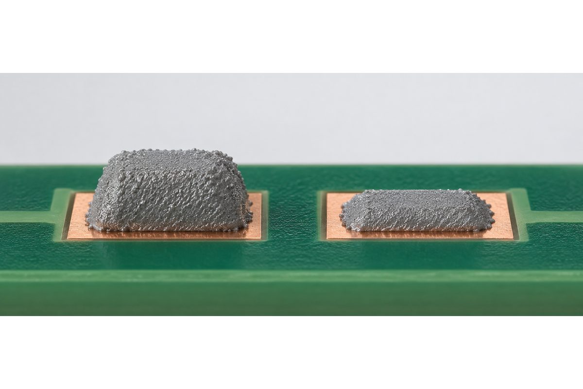
Provide Gerber or ODB++ data, drill files, fabrication drawing, stackup, BOM, approved alternates, centroid data, assembly drawings, polarity and orientation marks, stencil notes, panel requirements, firmware, calibration, and test instructions under one revision. Resolve conflicts before purchasing begins.
Use clear LED polarity, connector pin-one, channel, and assembly-side markings. Review mixed-technology parts, tall components, hand-solder access, heat-sensitive optics, conformal coating, staking, and cleaning restrictions. Panel rails, fiducials, tooling holes, support, and depanelization should match the actual line and enclosure constraints.
The PCB assembly process guide explains incoming control, paste printing, placement, reflow, inspection, through-hole operations, cleaning, programming, and testing. For a low-volume pilot, use production-intent steps where they affect the conclusion.
Profile reflow on the representative assembly
LEDs, connectors, large inductors, exposed-pad drivers, and copper planes can create different thermal masses. Attach thermocouples at representative high- and low-mass joints and temperature-sensitive components. Validate the profile against solder-paste and component limits rather than relying only on oven setpoints.
The thermocouple placement guide explains how to select risk locations, attach junctions, verify channels, and preserve evidence. Include the production panel, carrier, and conveyor support in the trial when they affect heating.
After reflow, inspect visible joints with AOI or microscopy as appropriate and use X-ray for hidden terminations where required. Separate assembly defects from design problems before changing the profile.
Build programming and functional test into the pilot
Define programming interface, power state, image, keys or configuration data, serialization, calibration, readback, and pass criteria. Protect the board from incorrect voltage or connector orientation. Log software and hardware versions with each unit.
A functional fixture should exercise each lighting channel, dimming command, communication interface, fault input and output, temperature sensor, and required protection behavior. Optical measurement can range from a controlled comparative fixture to formal photometric equipment depending on the decision. Define fixture repeatability and reference standards.
Design test points for appropriate contact, spacing, return access, and fixture support. Do not add a large branch to a fast or sensitive node merely for convenience. For very small lots, a connectorized test harness may be more appropriate than a full bed-of-nails fixture, but the method still needs revision control.
Use low volume to learn without losing configuration control
Choose a quantity that covers setup samples, engineering evaluation, mechanical integration, software work, environmental screening, destructive analysis, customer review, and retained references. Split lots intentionally if hardware variants are being compared. Do not mix experimental populations without serial identification.
Record defects and changes by unit, panel position, component lot, and process stage. Classify rework as manufacturing correction, engineering modification, or approved product change. A successful hand patch can support a redesign decision but should not quietly become the production architecture.
Hold a build review before ordering the next lot. Reconcile schematic, layout, BOM, firmware, drawings, test limits, and lessons learned. Close or explicitly defer every engineering query so the next build is not based on a folder of partially updated files.
Connect prototype evidence to environmental planning
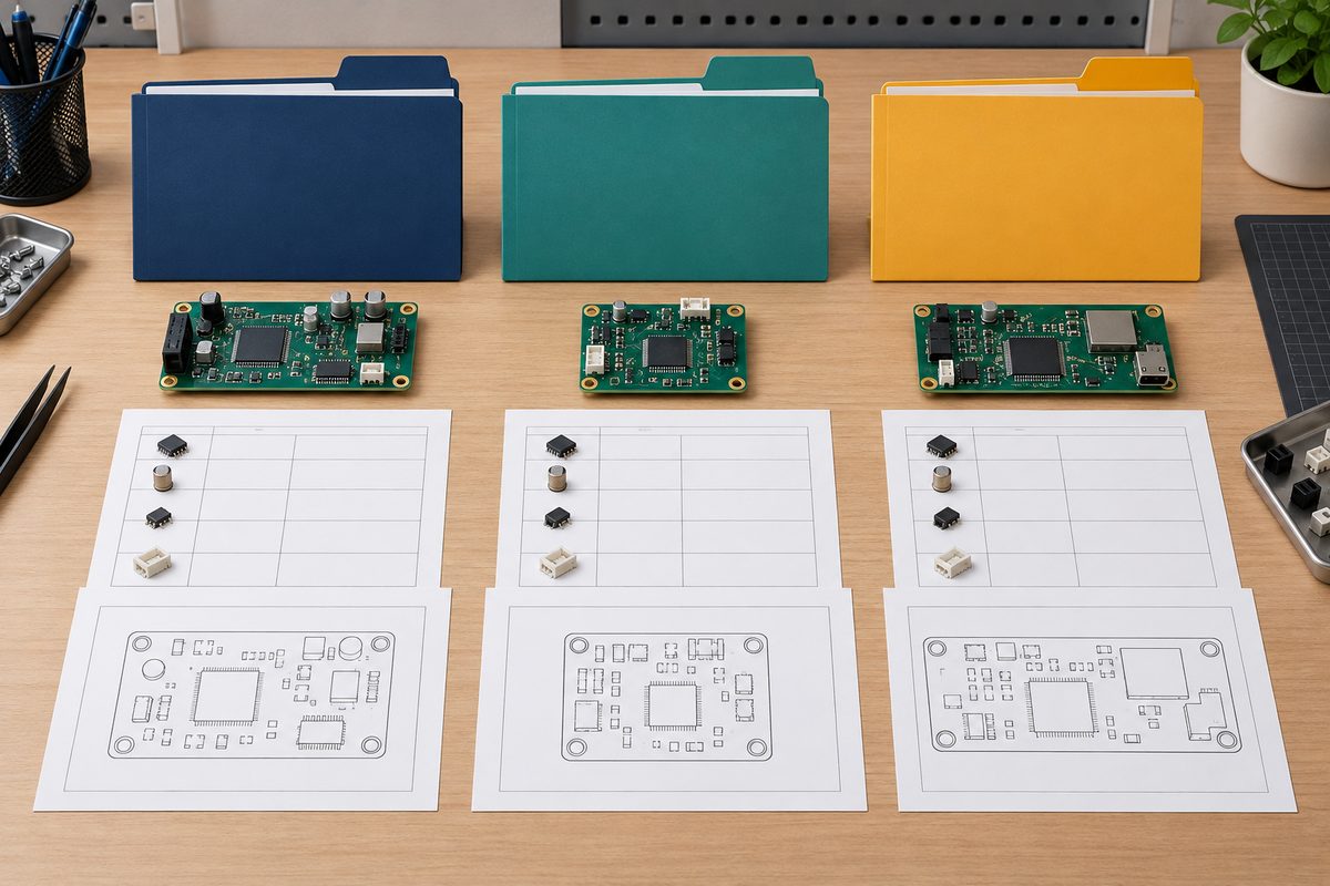
RTCA describes DO-160 as environmental and electromagnetic test procedures for airborne equipment. The responsible program authority selects the applicable document revision, categories, test levels, installation, operating modes, and approval path. A prototype PCB or component is not automatically “DO-160 qualified.”
Use the pilot to reduce risk before formal testing: confirm thermal margins, input-power behavior, vibration-sensitive mass, connector retention, waveform stability, emissions hotspots, susceptibility monitoring, protection paths, and functional test coverage. Preserve the exact board, BOM, software, enclosure, harness, grounding, optics, and operating configuration.
Changes after testing require impact assessment. A new LED driver, inductor, filter, PCB stackup, enclosure coating, harness, connector, firmware dimming mode, or thermal interface can affect earlier evidence.
What should be included in the RFQ?
Send the schematic, PCB files, fabrication drawing, stackup, BOM, alternates, placement file, assembly drawing, panel preference, mechanical model, connectors and harness, LED data and bins, firmware, calibration, optical targets, thermal assumptions, coating or staking, programming, inspection, functional tests, quantities, reports, and delivery dates.
For a first engineering lot, submit the design maturity, open questions, target quantity, and required evidence through the low-volume PCB assembly quotation path. Ask for identified assumptions rather than an unexplained unit price.
For a production-intent pilot, use the turnkey PCBA RFQ page to coordinate PCB fabrication, component sourcing, assembly, programming, coating, inspection, thermal profiling, optical checks, functional test, and delivery.
Aircraft cabin lighting prototype checklist
- Define what each prototype stage must prove.
- Freeze input power, LED strings, dimming, communications, and fault behavior.
- Use production-intent components where thermal, EMI, optical, or assembly results matter.
- Control LED bins, exact part numbers, alternates, and software versions.
- Design compact switching loops and deliberate thermal paths.
- Validate dimming, flicker, color, brightness, and fault recovery across operating conditions.
- Release consistent fabrication, assembly, programming, and test data.
- Profile reflow on the representative panel and assembly.
- Identify every unit and record inspection, calibration, and functional results.
- Review the pilot and close engineering changes before the next lot.
- Tie environmental evidence to the exact installed equipment configuration.
A fast prototype is one that answers defined questions and produces a controlled next revision. To combine PCB fabrication, component sourcing, low-volume assembly, programming, coating, inspection, thermal profiling, optical checks, and functional testing, submit the complete release through the AssyPCB RFQ page. Equipment compliance and certification decisions remain with the customer’s responsible engineering and approval organization.
Technical references: Texas Instruments LED-driver PCB layout guidance, Analog Devices AN-139 Power Supply Layout and EMI, and RTCA DO-160 overview.
Latest Blog
Contact Info
Phone: +86-755-82882936
Email: [email protected]
WhatsApp: +86-13570802455
Wechat: +86-13570802455
Address: 2nd floor,D Bldg.,Electric Link Technology Bldg.,Gongming,Guangming New Dist.,518106 Shenzhen, China