
CAF Testing: Evaluate Filament Risk Under Heat, Humidity, and Bias
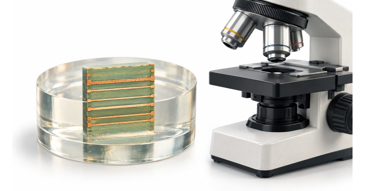
Table of Conent
Table of Conent
Conductive anodic filament (CAF) testing evaluates the risk of an internal electrochemical migration path forming through a printed board’s laminate under temperature, humidity, and electrical bias. The test does not simply ask whether a finished board is electrically isolated at room conditions. It uses defined test vehicles, conductor geometries, conditioning, chamber exposure, bias, insulation-resistance monitoring, and failure analysis to examine how material and manufacturing variables behave under sustained stress.
A useful CAF plan begins with the product risk: voltage between conductors, hole and feature spacing, orientation through the glass structure, laminate system, drilling and hole-wall condition, lamination history, contamination, assembly thermal exposure, and service humidity. The result should remain tied to the tested construction and method. A passing generic material coupon does not automatically qualify every stackup, via field, or finished product.
What is conductive anodic filament formation?
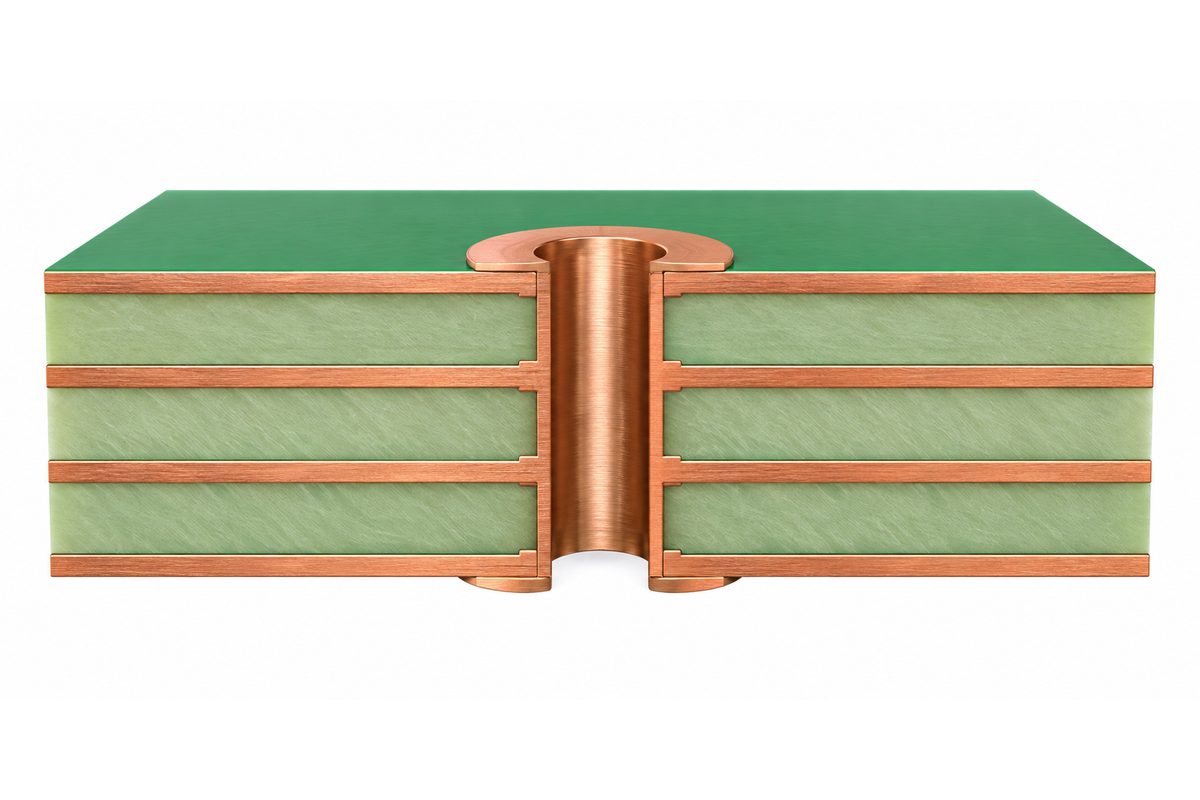
CAF is one internal electrochemical migration mechanism that can reduce insulation resistance within glass-reinforced laminate. Under suitable moisture and electrical-bias conditions, an electrically conductive path can develop along or near the glass-resin interface between oppositely biased conductors. The observed failure can involve plated holes, internal conductors, or other geometries represented by the test vehicle.
IPC-9691B explains that internal electrochemical migration concerns become more important as spacing decreases or voltage increases. It identifies contributors such as mechanical stress, laminate fracturing, ionic contamination, moisture before lamination, resin-to-glass bonding, hollow fibers, rough hole walls, and copper wicking. These factors interact; a failed coupon does not by itself name one root cause.
| Risk input | Why it matters | Evidence to preserve |
|---|---|---|
| Conductor voltage and spacing | Sets the electrical field across the insulation path | Net classes, maximum differential voltage, geometry |
| Laminate and glass construction | Influences moisture transport and internal interfaces | Manufacturer, grade, lot, prepreg and core details |
| Drilling and hole-wall quality | Damage can create or expose migration paths | Drill data, parameters, desmear, microsections |
| Lamination and moisture control | Affects resin wetting, bonding, and internal condition | Press cycle, material storage, bake and handling records |
| Assembly thermal exposure | Can alter laminate damage and moisture condition | Representative reflow or rework simulation |
How is CAF different from surface insulation resistance failure?
CAF is an internal migration phenomenon; surface insulation resistance (SIR) concerns conduction or electrochemical activity on the board surface. Both can appear as declining resistance under humidity and bias, so the test setup and failure analysis must distinguish them. Surface contamination, condensation, fixture leakage, or exposed conductors can confound an internal CAF test.
IPC-9691B advises users to understand surface-insulation behavior when interpreting internal electrochemical migration results. Test specimens, connection wires, chamber cleanliness, spacing, and protective masking should prevent surface paths from being mistaken for internal filaments. If resistance drops, locate the path before labeling the failure CAF.
A cross-section, optical analysis, or other material examination may be needed to connect the electrical event to the physical mechanism. The PCB microsection analysis practice explains why sample location, preparation, orientation, and interpretation must be controlled.
Which IPC method and test vehicle should be specified?
IPC lists IPC-TM-650 Method 2.6.25C for X-Y axis conductive anodic filament resistance testing. The method and its user guidance should be reviewed before selecting a coupon artwork. IPC explicitly notes that the user chooses the test-vehicle artwork after understanding the method; there is no single coupon that represents every product geometry.
Specify method revision, artwork, conductor orientation, plated-hole or feature spacing, layer construction, sample count, material identity, fabrication lot, assembly simulation, conditioning, bias, chamber conditions, monitoring interval, failure threshold, total duration, and analysis expectations. If the test is intended to qualify a product stackup rather than compare laminate candidates, the coupon construction should represent the relevant production materials and processes.
Do not cite only “CAF resistant material.” A laminate datasheet claim can support selection, but fabrication processes and geometry remain relevant. Ask what exact material, construction, glass style, resin content, treatment, and test method support the claim.
How should test specimens be prepared?
Preparation must avoid adding damage or contamination that changes the result. IPC-TM-650 2.6.25C includes prescreening for opens and shorts, representative assembly and rework simulation, cleaning, wiring, drying, and conditioning steps. Use the current method rather than copying isolated temperatures or times into a new procedure.
Preserve specimen identity from material receipt through fabrication, wiring, cleaning, chamber exposure, and analysis. Record panel location, artwork, stackup, drill tool, hole size, plating, laminate lot, prepreg lot where required, press cycle, desmear, thermal simulation, and any deviation. If a sample is damaged during wiring or preparation, mark it invalid rather than silently replacing its data.
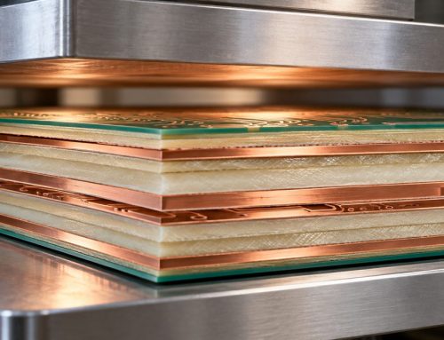
The PCB lamination guide describes how resin flow, moisture, contamination, copper distribution, and press control can affect the internal structure that CAF testing evaluates.
What do temperature, humidity, and bias do during testing?
Temperature and humidity promote moisture uptake and ionic mobility, while applied bias creates the electrical driving force across the selected insulation path. The chamber must maintain the specified environment without condensation or local airflow problems that invalidate the exposure. Bias and monitoring circuits must maintain channel isolation and avoid adding parallel leakage.
IPC’s method includes chamber placement and wiring guidance so airflow is not obstructed and condensation does not fall on specimens. Use calibrated chamber sensors and a monitoring system capable of the required resistance range and interval. Record excursions, power interruptions, channel faults, and fixture leakage separately from specimen failures.
Choose bias polarity and conductor grouping from the method and test-vehicle design. Reversing polarity or tying nets incorrectly can change which electrode is anodic and which internal path is stressed. A channel map should connect every data trace to specimen, pattern, and conductor pair.
How should insulation-resistance data be interpreted?
Interpret the complete resistance-versus-time trace, not only the final reading. A sudden drop, gradual decline, intermittent event, common-time change across channels, or chamber excursion can indicate different explanations. Apply the specified failure threshold and duration rules exactly, and retain raw data rather than only pass/fail summaries.
Compare patterns by geometry, material, process lot, panel position, and channel. Simultaneous drops across unrelated samples may indicate fixture, chamber, condensation, or measurement-system behavior. A repeated failure in one hole spacing or orientation supports a product-related pattern but still requires physical localization.
Do not convert test hours directly into field life without a validated acceleration model for the same mechanism and use environment. CAF testing is valuable for comparative qualification and risk evaluation, but heat, humidity, voltage, geometry, and material interactions make simple calendar-life claims unreliable.
What failure analysis is needed after a resistance drop?
First preserve the electrical data and specimen condition. Confirm the event is not an open wire, fixture leakage, surface path, chamber anomaly, or data-acquisition fault. Map the failed conductor pair and locate the suspected region using nondestructive methods where possible before sectioning.
Microsection orientation should follow the expected migration path and conductor geometry. Examine hole-wall damage, resin recession, glass-resin interfaces, copper wicking, cracks, contamination evidence, and the relationship to biased conductors. Because preparation can smear or remove evidence, use an experienced laboratory and retain control samples.
Separate lot disposition from root cause. A coupon failure can justify containment or additional evaluation, but permanent corrective action should follow evidence. Potential actions may involve material selection, hole spacing, voltage allocation, drill and desmear control, lamination, moisture handling, cleanliness, or assembly thermal exposure.
How can PCB design reduce CAF risk?
Increase spacing where electrical and layout requirements permit, especially between oppositely biased plated holes or conductors in high-humidity service. Avoid routing that concentrates high differential voltage across dense glass-fiber orientations without review. Coordinate hole size, annular ring, drill tolerance, layer registration, and pitch with realistic fabrication capability.
Material selection matters, but “CAF resistant” is not a substitute for design margin. Review laminate supplier data, glass construction, resin system, moisture properties, temperature rating, and documented CAF method. For high-risk products, consider product-representative coupons and ongoing lot or process controls rather than relying only on an initial material certificate.
Use the PCB DFM report guide to turn spacing, drill, material, and stackup concerns into explicit engineering dispositions before production files are released.
How do fabrication and assembly processes affect CAF risk?
Drilling can fracture resin-glass interfaces or create rough hole walls. Desmear and hole preparation affect damage removal and plating adhesion. Lamination controls resin wetting and internal bonding. Moisture exposure before pressing, contamination, copper wicking, registration, and repeated thermal excursions can influence the internal insulation system.
Assembly simulation matters because the finished board may see multiple reflow and rework cycles. IPC-TM-650 2.6.25C includes representative thermal cycling requirements. Define the actual assembly sequence, including double-sided reflow, selective soldering, wave exposure, repair, or downstream cure, and agree on the simulation that represents qualification.
For a CAF-sensitive project quotation, provide Gerbers, stackup, laminate requirements, drill files, conductor voltages, minimum spacing, expected environment, assembly cycles, quantities, coupon plan, method revision, and reporting needs through the PCB engineering review path. This lets fabrication and assembly assumptions be evaluated together.
If the coupon construction or laboratory scope is not yet defined, send the stackup, material candidates, conductor geometry, voltages, environment, assembly cycles, and required qualification evidence through the engineering quotation review before ordering test panels.
What should a CAF qualification report contain?
The report should identify the requirement, method and revision, test vehicle, artwork, construction, materials and lots, fabrication source and lot, sample preparation, assembly simulation, cleaning, conditioning, chamber setpoints and actuals, bias, wiring map, monitoring equipment, calibration, duration, failure criteria, raw traces, exceptions, failed-channel analysis, photographs, and disposition.
State what the result qualifies. A coupon result may support one laminate comparison, one fabrication process, a defined stackup family, or a specific product design. It should not be generalized beyond the tested evidence. Record requalification triggers such as laminate change, glass-style change, resin-content change, new fabricator, altered hole process, reduced spacing, higher voltage, or added assembly cycles.
The PCBA quote breakdown explains why coupons, environmental testing, laboratory analysis, and reporting should be separated from recurring board and assembly costs. Define sample ownership and destructive analysis before purchase-order release.

CAF test planning checklist
- Define maximum conductor differential voltage and service environment.
- Select the current test method, revision, artwork, and representative geometry.
- Identify laminate, glass construction, stackup, drill, plating, and fabrication lots.
- Include representative assembly and rework thermal exposure.
- Control cleaning, wiring, drying, conditioning, and specimen handling.
- Map bias polarity and every monitoring channel.
- Record chamber actuals, excursions, raw resistance traces, and fixture checks.
- Distinguish internal CAF from surface leakage and test-system artifacts.
- Perform location-specific failure analysis before approving corrective action.
- State the qualification scope and future requalification triggers.
CAF testing is most useful when it connects product voltage and spacing to representative materials, fabrication, assembly exposure, humidity, bias, and failure analysis. For a one-stop PCB assembly project, submit the controlled board package, BOM, stackup, material constraints, conductor voltages, environment, test method, coupon requirements, quantities, and assembly cycles through the RFQ page. The review can coordinate PCB fabrication, component sourcing, assembly, qualification coupons, laboratory testing, inspection, and delivery without treating CAF resistance as an unsupported material label.
Technical references: IPC-TM-650 test methods index, IPC-TM-650 Method 2.6.25C, and IPC-9691B CAF user guide.
Latest Blog
Contact Info
Phone: +86-755-82882936
Email: [email protected]
WhatsApp: +86-13570802455
Wechat: +86-13570802455
Address: 2nd floor,D Bldg.,Electric Link Technology Bldg.,Gongming,Guangming New Dist.,518106 Shenzhen, China