
Reliability Tests for Thermal Transfer Printer Control Boards
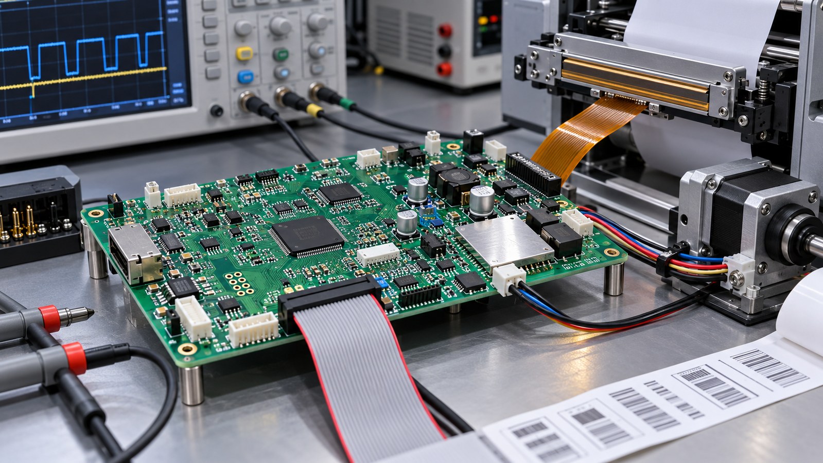
Table of Conent
Table of Conent
A reliable thermal transfer printer control board must be tested as part of the printing system, not only as a powered PCB. The most useful program verifies printhead pulse energy and sequencing, motor current and motion, sensor timing, power-rail stability, communications, fault recovery, and print output under the intended operating and environmental limits. It then carries the highest-risk measurements into a repeatable production test. The exact limits must come from the selected printhead, motor, power supply, mechanics, firmware, media, and product mission profile; a generic burn-in time cannot substitute for those requirements.
This approach matters because a board can pass continuity, programming, and a short bench print while still containing a marginal power path, timing error, thermal problem, connector weakness, or firmware recovery defect. Reliability testing should expose those weaknesses with measured loads, controlled stress, and objective pass/fail criteria before the design enters volume production.
Define reliability from the printer mission profile
Begin with the conditions the printer must survive and the work it must perform. Record supply tolerance, ambient range, humidity or condensation restrictions, print speed, dot density, darkness settings, ribbon and label combinations, duty cycle, roll diameter, motor acceleration, interface traffic, expected power interruptions, and service life. Separate continuous operation from short peaks. A shipping-label printer that produces intermittent batches has a different thermal and mechanical profile from an industrial coder running near continuously.
Convert that mission profile into requirements with a measurement, limit, sample plan, and failure response. For example, “prints at high speed” is not testable. A stronger requirement states the commanded speed, media construction, print-energy setting, allowed rail droop, allowed driver temperature, barcode grade or image metric, and number of consecutive labels. The reliability plan should also identify which limits come from component data sheets, system specifications, regulatory obligations, or engineering margins.
Map failure modes by controller-board subsystem
The controller contains several interacting stress domains. Testing each domain independently makes failures easier to diagnose, while combined-load testing reveals interactions that isolated checks miss.
Printhead power and timing
A thermal printhead converts electrical energy into heat at many small resistive elements. ROHM explains that applied energy depends on power and energization time, and that exceeding the printhead maximum can damage elements or shorten life. Its guidance also calls for logic supply before print supply during power-up, the reverse sequence during shutdown, and temperature control using the head thermistor. These are not abstract interface details: the controller firmware, gate timing, power switches, bulk capacitance, connector resistance, and copper distribution all affect the delivered pulse.
Measure print voltage at the board and near the head connector, strobe width, logic-to-print-supply sequence, pulse current, rail droop, recovery between strobes, head thermistor response, and the behavior when printing dense patterns. Include minimum and maximum supply, cold start, hot restart, and rapid changes between sparse and full-width content. Use the actual head model or an electrically representative load that reproduces resistance, inductance, and pulse demand.
Motor drive and media motion
The platen or ribbon mechanism can produce high startup current, current ripple, stall events, and supply noise. Texas Instruments notes that practical motor-driver current capability depends on die temperature, ambient temperature, PCB construction, and the duration of the load; protection thresholds alone do not establish a sustainable operating point. Capture phase current or bridge current during startup, acceleration, steady motion, reversal if applicable, heavy roll conditions, and controlled stall. Verify current regulation, fault reporting, recovery, and the temperature of the driver and nearby components.
Motion tests should correlate electrical data with label position, ribbon tracking, feed distance, slip, and missed steps. A board-level pass based only on motor rotation can hide intermittent connector resistance or insufficient torque margin.
Sensors, communications, and supervisory functions
Exercise gap, mark, cover-open, ribbon-end, temperature, and position inputs across their electrical tolerances. Check debounce, interrupt latency, pull-up values, connector faults, and ADC thresholds where applicable. Run USB, Ethernet, serial, or fieldbus traffic while the printhead and motor create their largest switching loads. Verify watchdog recovery, brownout behavior, nonvolatile settings, bootloader integrity, error logging, and safe outputs after an unexpected reset.
Build a layered reliability test program
No single test provides enough evidence. Use a layered sequence so inexpensive defects are removed before costly endurance or environmental work.
| Layer | Main purpose | Typical evidence |
|---|---|---|
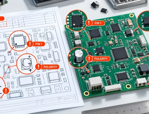
| Assembly screening | Find workmanship, polarity, placement, and solder defects | AOI or X-ray where justified, power-off resistance, controlled first power-up |
| Board functional test | Verify rails, programming, I/O, memory, drivers, sensors, and communications | Measured limits and serialized test log |
| System performance test | Prove printing, motion, timing, thermal response, and recovery with real loads | Waveforms, temperatures, current profiles, print samples, error logs |
| Fault injection | Confirm protection and safe recovery | Open/short simulations, brownout, stall, disconnected sensor, communications interruption |
| Endurance and environment | Reveal wear, marginal solder joints, connectors, and temperature-sensitive behavior | Cycles or operating hours with pre-, in-, and post-stress measurements |
| Production test | Screen every board using risk-based measurements | Fixture record linked to board serial number and firmware revision |
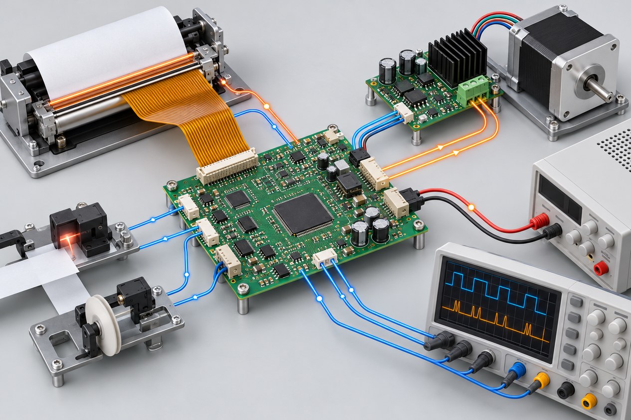
The design should expose the measurements this sequence requires. Include accessible test points for critical rails, reset, programming, communications, head control, motor current feedback, thermistor inputs, and fault outputs. Confirm fixture clearances and connector access during the PCB DFM report review, rather than discovering after fabrication that a bed-of-nails probe collides with a component or enclosure feature.
Measure the board under realistic combined loads
A realistic stress case usually combines high print density, rapid label feed, active communications, and the least favorable allowed supply and temperature. Measure at the load, not only at the bench supply. Cable and connector resistance can cause the printhead rail to sag even when the source looks stable. Oscilloscope captures should use sufficient bandwidth and a safe ground method, with current probes or characterized shunts sized for the pulse profile.
Use a repeatable diagnostic pattern containing solid bars, fine lines, alternating dots, small text, and barcodes. The pattern should force known printhead loading while making timing and alignment defects visible. Keep reference images or graded samples, but do not use subjective appearance as the only acceptance method. Where the product requires barcode performance, specify the verifier method and threshold. Track darkness uniformity, missing dots, horizontal or vertical registration, feed length, and error counts.
Thermal measurements should include the head substrate or thermistor, motor driver, power switches, regulators, connectors, and high-current copper. The board thermal path must be evaluated with the actual enclosure and airflow. The same principle used when selecting PCB vias for current and heat flow applies here: copper, vias, interfaces, and cooling hardware operate as one path, so a cool bench test with an exposed board can overstate margin.
When the schematic, stackup, load definitions, and acceptance limits are ready, submit the Gerbers, BOM, placement files, firmware build, interface pinout, and reliability test matrix for a manufacturing and test review. This lets fabrication, component sourcing, assembly, fixture access, and test coverage be evaluated against the same controlled requirements before the build is released.
Use fault injection to verify protection and recovery
Fault injection should be controlled, current-limited, and tied to a defined expected response. Useful cases include printhead disconnected, one sensor open or shorted, motor stalled, communications removed during a job, supply ramped slowly, rapid power cycling, brownout during nonvolatile memory activity, and overtemperature input simulated at the thermistor channel. Do not apply a destructive short merely because the driver advertises protection; use the component data sheet, safe fixture limits, and a staged procedure.
For every injected fault, record detection time, affected outputs, user-visible or host-visible error, thermal behavior, retry policy, and state after recovery. The board should not leave the printhead energized, repeatedly hammer a stalled motor, corrupt settings, or restart into an unsafe output state. Re-run a standard print after recovery and compare the electrical and print results with the pre-fault baseline.
Plan environmental and mechanical tests around real risks
Environmental standards provide methods, not an automatic product qualification recipe. IEC 60068-2-78 addresses steady-state damp heat, while IEC 60068-2-64 addresses broadband random vibration. Select severities from the product specification, installation, transport, and failure physics. A test that is much harsher than the intended life can create an irrelevant failure; a convenient mild test can miss the mechanism that matters.
Temperature cycling can expose solder-joint, connector, and material-expansion weaknesses. IPC-9701B describes thermal cycling for surface-mount attachment fatigue and stresses that accelerated results require appropriate acceleration factors; they are not automatically equivalent to field life. Instrument representative boards and confirm the assembly actually reaches the intended temperature extremes and dwell conditions. Preserve failure samples for electrical localization, microscopy, X-ray, cross-sectioning, or other analysis appropriate to the defect.
Vibration testing should use realistic board support, connector mass, cable routing, and mounting torque. Otherwise, the fixture may dominate the result. Humidity exposure should be followed by insulation, leakage, corrosion, sensor-offset, and functional checks, with attention to condensation restrictions. When a change is introduced after initial qualification, use a documented DVT change review to select regression tests based on which requirements and failure mechanisms the change can affect.
Separate design validation from production screening
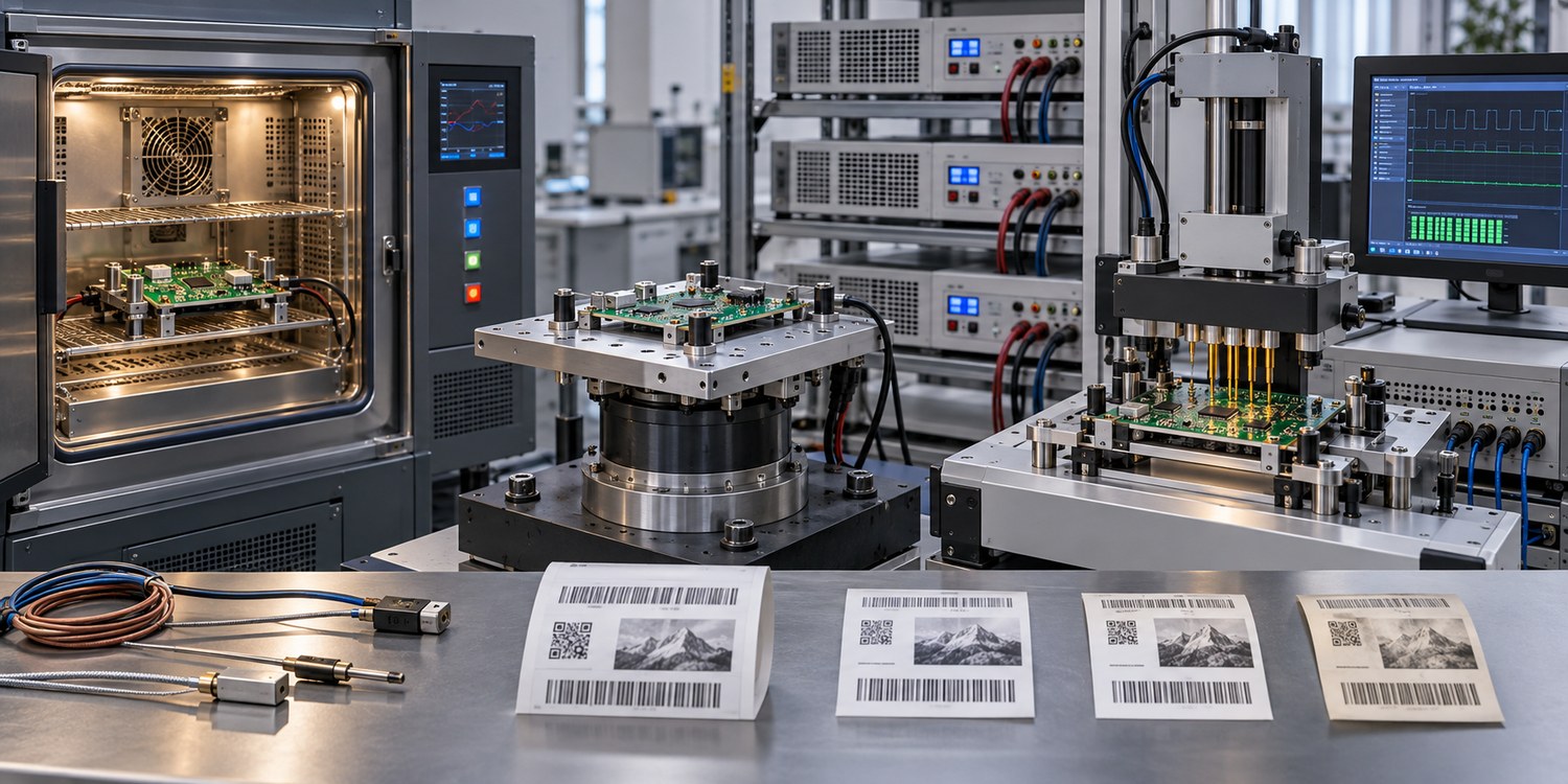
Design validation asks whether the product architecture meets its requirements with margin. It uses instrumented boards, corner conditions, fault injection, endurance, environmental exposure, and failure analysis. Production screening asks whether each manufactured unit matches the qualified design and process. It should be faster, deterministic, and resistant to operator variation.
Translate high-risk validation findings into production controls. If testing shows that printhead rail resistance predicts weak output, measure the relevant voltage drop or current pulse in the fixture. If a motor connector intermittently opens under load, include loaded motion and connector verification. If firmware and hardware compatibility is critical, log the programmed image, board revision, calibration data, and test-software revision. Keep the production test limit inside the validated operating boundary while accounting for measurement uncertainty and normal component tolerance.
A production fixture may include boundary-access probes, programming, loopback loads, sensor emulators, motor or electronic loads, and a limited printhead check. Define fixture calibration, golden-unit control, maintenance intervals, probe replacement, software versioning, and retest policy. The fixture wiring and board orientation should follow the released PCB assembly drawing and build notes so variants and do-not-fit components are handled correctly.
Control samples, limits, and failure evidence
A test plan needs more than a list of stresses. For each test, identify the requirement, sample size, board and firmware revision, preconditioning, fixture, instrumentation, calibration status, stress profile, measurement points, pass/fail limits, data format, and disposition for failures. Include unpowered controls or unstressed comparison units when they help separate aging from measurement drift.
Choose sample quantities using product risk, expected failure distribution, confidence goals, and available evidence. Avoid claiming that a small number of boards “proves” a lifetime without a justified model. Reliability growth comes from finding mechanisms, correcting root causes, and repeating the affected evidence. Maintain traceability among the failure record, schematic location, component lot, assembly lot, test condition, waveform, and corrective action.
Test scope also affects procurement comparisons. A fixture line item is not comparable unless suppliers are quoting the same interfaces, loads, limits, data retention, calibration, ownership, and reuse. Normalize these assumptions when you compare PCB quotes by test scope and delivered cost.
Release a manufacturing-ready reliability package
Before the build, release the approved schematic, Gerbers or ODB++, stackup, BOM with alternates, placement data, assembly drawing, firmware and programming method, connector pinout, controlled load definitions, test matrix, acceptance limits, sample plan, and failure-report format. Identify which equipment and loads the customer supplies, which fixtures the manufacturer develops, and who owns validation versus production-test approval.
For a complete PCBA evaluation, provide the released design package, target quantity, printer interfaces, operating profile, validation matrix, and production test requirements. OrinewPCB can then review PCB fabrication, component sourcing, assembly, programming, fixture access, and test deliverables as one controlled scope rather than treating reliability as an undefined final inspection.
Reliability test checklist
- Define supply, temperature, humidity, vibration, duty-cycle, media, speed, and service-life conditions.
- Measure printhead voltage, current, strobe timing, power sequencing, thermistor response, and output quality.
- Measure motor current, motion accuracy, stall protection, driver temperature, and recovery.
- Exercise sensors, communications, watchdog, brownout, memory, firmware update, and safe-state behavior.
- Run combined-load tests at operating corners, not only isolated room-temperature checks.
- Use controlled fault injection with defined expected responses and post-fault verification.
- Select environmental severities from the mission profile and relevant failure mechanisms.
- Carry the most predictive measurements into a calibrated, serialized production fixture.
- Link every failure to board revision, firmware, lot, condition, evidence, root cause, and corrective action.
Conclusion
Thermal transfer printer board reliability is demonstrated by controlled evidence across the complete electrical and mechanical workload. The strongest plan starts from the mission profile, measures printhead energy and sequencing, observes motor and power behavior, verifies sensing and recovery, applies justified environmental stress, and converts design findings into production controls. That sequence produces evidence that engineers can diagnose and procurement teams can define in a build scope.
References
- ROHM: Maximum Ratings and Standard Printing Conditions for Thermal Printheads
- ROHM: Resistance of Thermal Printheads and Resistance Variation
- Texas Instruments: Understanding Motor Driver Current Ratings
- IPC-9701B: Thermal Cycling Test Method for Fatigue Life Characterization of Surface Mount Attachments
- IEC 60068-2-64:2026, Broadband Random Vibration
- IEC 60068-2-78, Damp Heat, Steady State
Latest Blog

Contact Info
Phone: +86-755-82882936
Email: [email protected]
WhatsApp: +86-13570802455
Wechat: +86-13570802455
Address: 2nd floor,D Bldg.,Electric Link Technology Bldg.,Gongming,Guangming New Dist.,518106 Shenzhen, China