
Arduino vs STM32 vs ESP32: Choose for Production
Table of Conent
Table of Conent
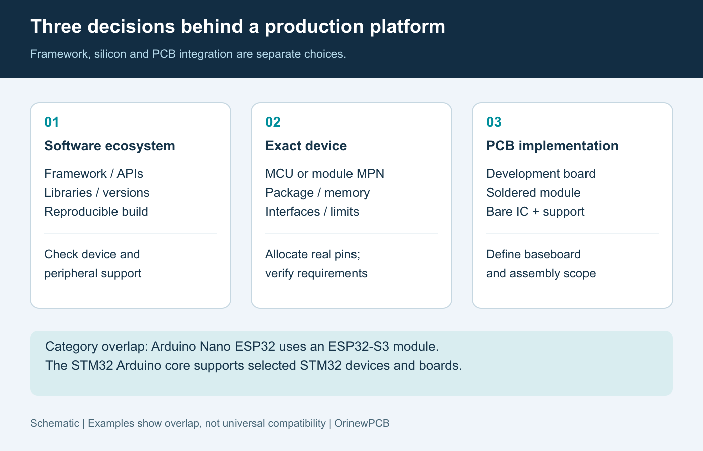
Arduino vs STM32 vs ESP32 is a useful starting question, but production selection requires three separate decisions: the software ecosystem, the exact microcontroller, and the hardware you will assemble. Arduino can be part of an STM32 or ESP32 solution. Choose the combination that meets your product’s timing, interfaces, power, connectivity, and maintenance requirements, then prove those requirements on the proposed production circuit.
A development board that runs the application establishes feasibility. It does not establish that the same firmware, power supply, antenna environment, or programming process will work after the design moves to a custom PCB. For an OEM team, the strongest comparison ends with an approved part number, measured evidence, and a reproducible assembly package.
Separate the ecosystem, MCU, and physical implementation
Arduino, STM32, and ESP32 are not three equivalent component specifications. Separate what runs the software from what appears on the bill of materials before comparing performance or cost.
Arduino provides boards and a software ecosystem. Its boards use different processors: the UNO R4 Minima uses a Renesas RA4M1, while the Nano ESP32 uses an ESP32-S3 through a NORA-W106 module. Therefore, “Arduino or ESP32?” can describe two parts of the same implementation.
STM32 is a broad STMicroelectronics MCU portfolio, not a single set of memory, package, or radio specifications. ST’s STM32 portfolio includes wireless families, so “STM32 has no radio” is not a valid family-wide assumption. The STM32 Arduino core also supports Arduino development on supported devices and boards. Confirm the particular board, peripheral, and library support rather than assuming portability.
| Selection layer | What it establishes | What must still be decided |
|---|---|---|
| Framework and libraries | APIs, dependencies, development workflow | Supported device, peripheral behavior, maintenance and reproducible build |
| Exact MCU or module part number | Available interfaces, memory, package and specified operating limits | Pin allocation, circuit design and application performance |
| Development board, module, or bare IC | Which support circuitry is purchased and which is designed | Baseboard constraints, assembly access, enclosure effects and production test |
Choose against product constraints, not a family label
The useful winner is the candidate that satisfies your mandatory requirements with evidence. Screen exact devices first; compare development convenience and manufacturing effort after eliminating incompatible options.
List the required signals before choosing a package. Count timers, capture channels, serial interfaces, analog inputs, and programming pins, then allocate them simultaneously. A device can advertise every required peripheral yet expose incompatible alternate functions on the same pins in the selected package. Check electrical levels separately; a familiar connector or library does not establish input tolerance. Our open-drain and push-pull interface guide explains why output topology and pull-ups matter at that boundary.
| Product constraint | Evidence to obtain | Decision consequence |
|---|---|---|
| Control timing with communications active | Measured response and jitter under the specified simultaneous workload | Change scheduling, peripherals, device, or architecture if the limit is missed |
| Analog sensing | Input-range review and measurement with the actual sensor, reference and board layout | Resolve signal conditioning and error budget before selecting by ADC bit count |
| Battery operation | Current profile across sleep, wake, measurement, transfer and retry states | Compare the complete duty cycle and supply capability, not a chip sleep figure alone |
| Wireless link | Selected part’s protocol support and checks in the intended enclosure | Reserve the module’s specified antenna region and validate the integrated product |
| Field updates and factory programming | Verified image, accessible programming connections and a tested recovery procedure | Provide fixture access and define which settings are written at which stage |
| Repeat orders | Exact approved part numbers, current sourcing checks and substitution restrictions | Keep an unapproved “compatible” module or MCU out of the production BOM |
Decide what belongs on the production PCB
Choose a development board, a soldered module, or a bare IC by the work each option leaves to your team. Compare the complete assembly and validation scope rather than a retail board price against an MCU line item.
Retaining a development board may preserve a proven prototype configuration, but its connectors, mounting, supply path, and programming behavior become product requirements. Confirm how it will be secured, supplied, inspected, and replaced. Do not silently substitute a similar-looking board with different support circuitry.
A module can retain selected support circuitry while reducing the custom design boundary. It still needs a suitable baseboard. Espressif’s ESP32-S3 PCB layout guidance addresses module and antenna placement. Apply the guidance and drawing for the actual module; do not copy an antenna clearance from another ESP32 product. Connectors, copper, enclosure material, and nearby structures belong in that integration review.
A bare-IC implementation moves more responsibility into the PCB design: supply and decoupling, clocks where required, reset and boot configuration, programming access, and RF circuitry where applicable. Its smaller component price can be offset by design iterations or added test effort. Obtain comparable quotations with the same quantity, sourcing scope, test requirements, and released files before claiming a cost advantage.
If the integration form is still changing, share the candidate BOM and board files with the build quantity and substitution constraints so the sourcing and assembly scope can be clarified before the configuration is frozen.
Prove the choice with the actual firmware and load states
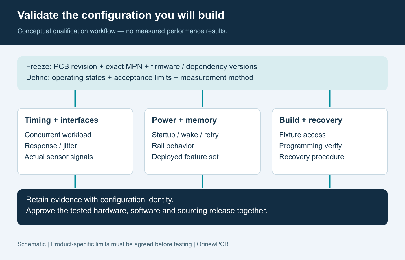
Qualification should exercise the proposed hardware and firmware together. A benchmark or demonstration sketch cannot establish the behavior of a different application, library set, or operating state.
Define acceptance limits before the run. For example, a hypothetical connected actuator controller needs a defined command-response limit while communication traffic and sensor processing are active. Test that combination rather than proving each task in isolation. Record firmware identity, toolchain settings, enabled services, supply conditions, and the measurement method alongside the result.
Distinguish a peripheral’s hardware capability from when the application services it. Measure the signal or output that matters to the product. If a deadline is missed, investigate interrupt priorities, blocking calls, task scheduling, data transfer, and peripheral configuration before treating a faster processor as the cure. A separate communications processor is another architecture to evaluate, with its own interprocessor protocol and failure handling.
Measure supply behavior at the relevant board rail during transitions as well as steady operation. Include communication retries, startup, and wake events when they occur in the real duty cycle. If the prototype’s regulator, USB circuitry, or indicator LEDs are removed, repeat the power evaluation on the revised circuit. Chip-level current and development-board current describe different boundaries.
Check memory usage with the deployed features enabled and define the reserve the product needs for updates and abnormal conditions. A successful minimal program does not prove capacity for the final communications stack, buffers, application, and update scheme. Retain the configuration with the test record so another engineer can reproduce the decision.
Exercise recovery as a separate test case. Identify what the product should do after an interrupted update, a lost communications link, or a supply interruption, where those events are relevant. Record the initial state, the stimulus, the expected response, and the observed result. Separate an application defect from an inability to reach the programming interface: they require different corrective actions. Keep a known recovery image and the required access instructions with the qualification package.
Freeze the hardware, software, and sourcing configuration
The production unit must be identifiable as the configuration that passed qualification. Control the MCU or module, firmware, programming instructions, and approved substitutions together.
Specify the complete manufacturer part number, package, and applicable module variant in the BOM. Record external memory and other configuration-dependent parts separately. A change in memory capacity, pin allocation, antenna option, or boot configuration can require circuit, firmware, and test changes even when the replacement remains in the same product family.
Maintain an approved BOM substitution process that identifies which changes require engineering review and requalification. Recheck sourcing at the planned build quantity; neither a broad product portfolio nor a distributor listing proves availability for a particular order. Keep commercial availability checks dated and separate from technical equivalence approval.
For software, retain the buildable source revision, framework or board-package version, library versions, configuration files, and toolchain settings. Identify the released binary with a checksum and specify the target hardware revision. Include the programming sequence, required files, verification method, and any product-specific configuration. Define access and recovery before enabling irreversible device settings; use the selected device’s documentation for those settings.
The production instruction should distinguish common firmware from unit-specific configuration. State how a unit is identified, how the correct image is selected, and what record proves programming verification. If a failed unit is reworked, define whether programming and functional checks must be repeated. This prevents a correct PCB assembly from being released with the wrong software identity or an incomplete rework record.
Separate design qualification from routine production acceptance. The former establishes that the design meets product requirements; the latter checks the agreed properties of each assembly or lot. Our PCB test-planning guide helps connect requirements to methods and retained records. Agree programming, fixture development, functional checks, and responsibility for specialized measurements explicitly; do not assume they are included in every assembly order.
Release the platform as a buildable assembly
A production-ready platform choice ends in a controlled build package, not a family ranking. Select the exact candidate that meets the product’s measured requirements, retain the evidence, and make the approved configuration reproducible.
Package the fabrication files, BOM, placement data, assembly drawing, firmware release, and agreed test instructions under consistent revision identifiers. Include quantity, sourcing restrictions, and acceptance requirements. A full-turnkey PCB assembly scope connects board fabrication, component sourcing, and assembly; the order must still identify who supplies firmware, fixtures, and the product-specific test limits.
For a build ready to move forward with OrinewPCB, provide the controlled assembly package and test requirements so the fabrication, sourcing, assembly, and agreed testing scope can be reviewed together. Arduino, STM32, and ESP32 become useful choices when the resulting hardware, software, and purchasing decisions describe the same product.
Use the current documentation for the exact device, module, board revision, and software configuration being released.
Latest Blog
Contact Info
Phone: +86-755-82882936
Email: [email protected]
WhatsApp: +86-13570802455
Wechat: +86-13570802455
Address: 2nd floor,D Bldg.,Electric Link Technology Bldg.,Gongming,Guangming New Dist.,518106 Shenzhen, China