
Flight Data Recorder PCBA Checklist: Verify Data After a Power Interruption

Table of Conent
Table of Conent
A flight data recorder PCBA checklist should show what data can be read back after a power interruption. Feed the board a known, changing input, interrupt power while it is writing, and compare the recovered records with the input log. Identify the last valid record before the interruption and the first valid record after recovery. Check that both carry the expected values and timing, and that earlier data remains readable. Set the allowable gap, restart behavior, and other limits from the recorder’s approved project requirements.
This checklist is for engineers and buyers preparing a recorder board for assembly or a design change. Board acceptance provides evidence for a defined hardware and firmware configuration. The recorder design authority sets the equipment qualification scope and decides which evidence transfers to the installed system.
Separate board acceptance from equipment qualification
Use the board acceptance test to check repeatable manufacturing and programming outcomes. Use the equipment qualification plan to establish how the representative recorder behaves in its specified configuration and environment.
The FAA guidance on airborne equipment environmental qualification describes DO-160 as a way to demonstrate airborne equipment performance under environmental conditions. The program determines the applicable revision, categories, operating modes, and acceptance criteria. A recorder test article can depend on its enclosure, mounts, bonding, harness, power source, firmware, and storage configuration. Identify those dependencies before using bench data to support an equipment test decision.
EUROCAE’s crash-protected recorder standards cover another part of the program: crash-protected airborne recorder systems. Treat crash protection and post-event recovery as equipment and system questions. An assembly traveler, a memory component data sheet, and an environmental test report each answer different questions. Keep their scope and owning authority explicit in the release record.
Start the manufacturing test plan by drawing the board boundary. If the board receives an already formatted stream, exercise the actual input and verify that the correct stream survives storage and readout. If a separate unit performs acquisition or the storage module sits outside the board, identify the representative hardware or simulator. Document which path was exercised and which parts of the recorder remain outside the fixture’s coverage.
Test what happens to the recording at power loss
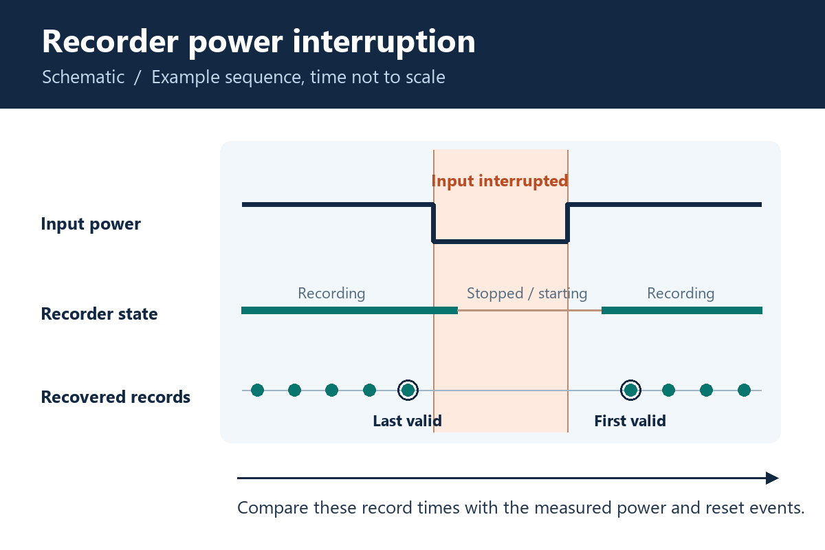
Apply a controlled interruption while the recorder is storing known data. Measure the disturbance at the board input and compare it with the reset or power-good signal and the recovered data. Those measurements let the team tell a clean restart from a restart that loses or mislabels data.
Log the stimulus on a test system that stays powered when the recorder loses power. Start with a clean baseline using the released build and firmware. Then, for engineering characterization, cut at phases that can expose different failure modes. If the board uses a write cache or a journal, include a write or update in progress. Where the project allows a shortened production test, choose a repeatable case based on that characterization and write down the coverage it provides.
| When to interrupt | What to preserve | What the result helps decide |
|---|---|---|
| Between writes | Baseline export, interruption waveform, restart time | Whether the recorder restores normal capture and preserves the previous records. |
| During a record or metadata update, where observable | Raw export around the interrupted operation and status of earlier records | Whether the design detects or recovers a partial update as required. |
| At a storage wrap boundary, if the design uses a circular buffer | Record identities on both sides of wrap and restart | Whether the oldest and newest recoverable records remain ordered according to the design. |
| During restart, if required by the project | Reset sequence, last valid record, first valid new record | Whether a second interruption affects stored history or creates an apparent valid session too early. |
Specify the test supply, fixture harness, measurement point, triggering condition, storage state, and reader version. Use an approved profile for the fixture. If the program requires a DO-160 test, the equipment test plan governs its conditions and reporting. If fixture coverage is still open, share the interruption profile and readout limits with the intended build so the assembly team can review test access, fixture needs, and the results it can deliver.
Correlate the input with the recovered flight data
Compare decoded records with the independently logged input, and keep the raw export so the comparison can be repeated. Matching files alone only establish agreement with a reference file. Confirm that the reference and decoder represent the released parameter mapping.
In NTSB’s explanation of flight data recorders, parameters such as altitude, airspeed, and heading illustrate the data used in reconstructing a flight. The FAA guidance on digital flight data recorder systems explains the role of correlation between recorded values and engineering units, and discusses the quality of data readout. For a board fixture, apply that principle to the interfaces and parameters within the test scope. Record the stimulus ID, mapping revision, and expected units alongside the board serial number.
For example, use a rising value, a falling value, and a discrete change at a known point. Choose inputs that remain distinguishable when the stream is decoded. A record with a valid timestamp but an old payload will stand out if the input changes across the interruption. A correct raw code with the wrong displayed value points the investigation toward mapping, scaling, or the reader. A missing raw record points the investigation toward the input, storage, or export path and calls for additional isolation.
Compare the last valid record and the first valid new record on a common time reference. When the fixture and recorder use separate clocks, log a marker both can observe and state how the comparison accounts for clock offsets. In the result record, separate missing samples, invalid samples, and values that the design deliberately holds. Use the project criteria to decide whether each is acceptable. Reviewing manufacturing test coverage for complex PCBAs helps teams assign programming, structural inspection, and functional coverage to the correct stations.
Control changes that can invalidate the readout evidence
Route a proposed change by the behavior it can affect. A pin-compatible flash device, a different reset supervisor, or a new decoder may change the meaning of an earlier pass. Tie the disposition to the approved hardware, firmware, and test configuration.
| Proposed change | Potential effect | Evidence to request before release |
|---|---|---|
| Storage device or storage firmware | Write timing or recovery behavior changes under interruption. | Repeat baseline export and targeted interrupted-write tests with the proposed combination. |
| Input protection, supply, or reset component | Reset timing or available write time shifts as the input falls. | Compare power, reset, and recovered records under the applicable fixture profile. Send equipment-level effects to the design authority. |
| Connector, shield termination, or fixture harness | The board sees different signal, return, or power conditions. | Check interface behavior and the disturbance at the board connector. Review representative equipment configuration if the product changes. |
| Parameter map, test script, or readout tool | The fixture can pass the wrong values or conceal a gap. | Reprocess a known raw export, rerun controlled stimulus, and retain both tool and mapping revisions. |
Identify the serial number and as-built component variant on each retained result. A shared PCB part number can cover several assembly populations, so include the approved variant and any authorized substitutions in the test record. Apply the same discipline when controlling PCB assembly variants for production. When a proposed substitute affects the tested behavior, have the project owner approve the evidence and scope before it enters the build.
Specify what the supplier should build and test
Quote assembly and recorder functional testing as distinct deliverables. A supplier needs enough detail to price the fixture, programming, per-unit test time, and evidence retention, as well as the board and components. Clarify which assets the buyer will supply and which the supplier should develop.
The release package should include the fabrication files, BOM with alternate rules, placement data, assembly drawing, build quantity, and delivery requirements. Add the firmware identifier and programming instructions, the stimulus and expected readout, the limits for each production test, and an example of the result file. Identify how to handle failed or interrupted tests, how to retain original and retest results, and who can approve a deviation.
Ask the supplier to separate fixture engineering from recurring test costs and to call out any equipment test or specialized readout tool outside its scope. The turnkey PCB assembly scope gives procurement a starting point for combining fabrication, sourcing, and assembly. When those files and requirements are ready, send the released build files and acceptance test plan with the requested test deliverables so they can be evaluated with the production quote.
Release the board with a reproducible test record
A useful acceptance record lets another engineer repeat the same stimulus, find the interruption in the captured waveform, and explain the last and first valid records in the readout. Release the board against the agreed limits and retain the exact assembly, firmware, fixture, and decoder revisions with the result. Carry any unresolved qualification or installation questions to the recorder design authority with the evidence needed to decide the next test.
Latest Blog



Contact Info
Phone: +86-755-82882936
Email: [email protected]
WhatsApp: +86-13570802455
Wechat: +86-13570802455
Address: 2nd floor,D Bldg.,Electric Link Technology Bldg.,Gongming,Guangming New Dist.,518106 Shenzhen, China
